Contact, How to replace the dust seal, Installing the air tube – KEYENCE GT2-100 Series User Manual
Page 7: How to replace the contact
7
GT2-100-M-E
● Mounting with the mounting holes
Mount the GT2-H32(L)/H50/A32/A50 on the side of a table using
the mounting holes on the side of the unit body.
■
Installing the Air Tube
● Compatible air tube
Use a tube with the following specifications.
● How to Attach/Detach the Air Tube (GT2-PA12K/PA12)
•
Attaching the air tube
Insert the air tube into the air supply hole on the relay connector.
•
Detaching the air tube
To detach the air tube, pull the air tube in the direction of the arrow,
as indicated in the figure below.
● How to Attach/Detach the Air Tube (GT2-A12K(L)/A12(L)/A32/A50)
•
Attaching the air tube
Feed the tubing into the socket until it bottoms out (about 1/2").
The socket will ensure a tight seal around the tubing.
•
Detaching the air tube
To detach the air tube, (1) press down on the release ring, (2) pull out the tube.
● For GT2-A12K/A12/A32/A50 when an IP67 enclosure rating is required
To maintain an IP67 enclosure rating, the following must be satisfied:
•
Firmly connect tubing with
2.5 mm inner diameter to the exhaust
port until it bottoms out.
Ensure that the tube end is free of dirt or water.
•
Tighten the screw of the exhaust valve with a torque of 0.5 to 0.6 N•m.
If the screw is loose, the IP67 rating cannot be guaranteed.
● Adjustment of Spindle Movement Speed
To adjust the spindle movement speed, install a speed controller between
the cylinder and the air supply. Using OP-87970 is recommended.
Contact
This section describes how to replace the contact, and how to mount the lift lever.
■
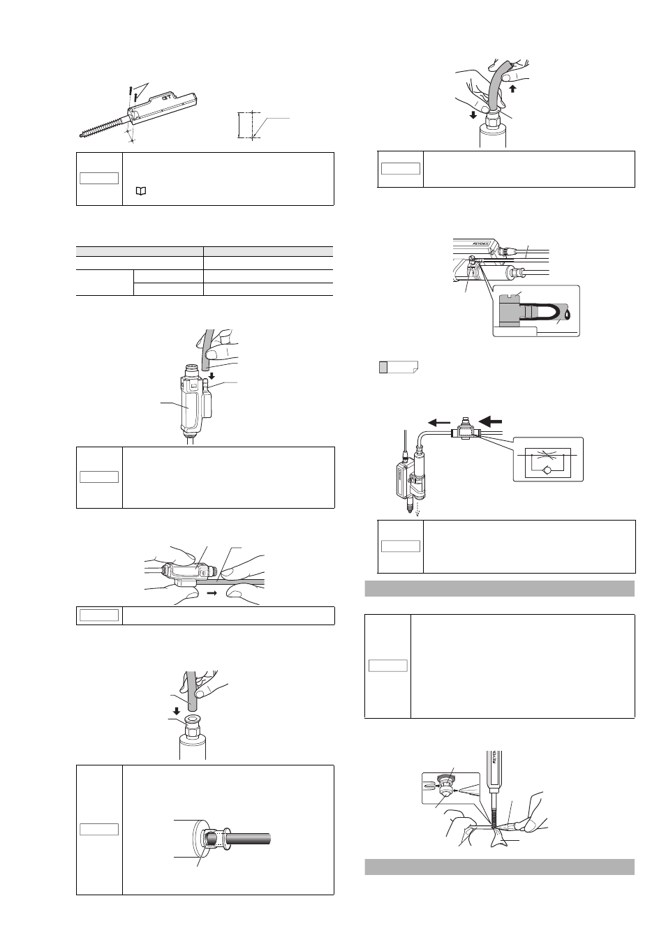
How to replace the contact
While securing the spindle with the accessory key wrench, detach the
contact with pliers. Then attach a new contact.
How to replace the dust seal
Refer to the instruction manual included with the replacement dust seal
(OP-87932).
NOTICE
• Roughness of the mounting surface may cause the
sensor to tilt, and sufficient accuracy may not be
obtained. When performing a high-accuracy
measurement, use a jig to mount the sensor head.
"Mounting directly to a jig" (Page 5)
• Apply tightening torque between 1.2 and 1.5 N•m.
Item
Description
Recommended tubing material
Urethane
Tubing size
Outer diameter
4 mm
Inner diameter
2.5 mm
NOTICE
• For best results, cut the end of the tube at a right angle,
and ensure that the outer perimeter is not damaged,
and that it still maintains a circular cross section.
• If the tube is not properly inserted, air leakage may result.
• After attaching, pull on the tube to make sure it is secure.
• Use a urethane tube. Make sure it also has a bending
radius of at least 50 mm.
NOTICE
Before detaching the tube, be sure to stop any air flow.
NOTICE
• For best results, cut the end of the tube at a right
angle, ensure that the outer perimeter is not
damaged, and that it still maintains a circular cross
section.
• If the tube is not properly inserted, air leakage may
result (see figure below).
• After attachment, pull on the tube to make sure it is
secure.
M4 screws
(Mounting hole dimensions)
Mounting diagram
23
±0.15
mm
4-M4 tap
Air tube
Air supply hole
Relay connector
Relay connector
Air tube
Air tube
Coupling socket
Tube end
NOTICE
• Before detaching the tube, be sure to stop any air flow.
• Press down on the release ring evenly from both sides, and
pull the tube out. Uneven pressure may result in damage to
the tube or damage to the operation of the air cylinder.
Reference
By loosening the screw of the exhaust valve, you can
change the exhaust port angle.
NOTICE
• To further decrease spindle movement speed, use
a coil-shaped tube (OP-87986) or similar to
increase the distance between the air supply hole
and the speed controller.
• The speed controller will not operate if installed in
the reverse direction.
NOTICE
• Detach the sensor head from the device or fixture
(metal plating, etc.) before replacing the contact.
• When applying pliers to the contact, be sure not to rotate
the main part and cover the contact with a cloth.
• Never apply tightening torque over 0.2 N•m when
attaching a contact.
• Fix the roller contact (OP-77680) or the offset contact (OP-77683)
with the fixing nut in the same direction as in actual use.
• Applying an adhesive, a thread locking agent, is
recommended to prevent the nut from loosening.
• Position the roller contact carefully in the proper direction.
Care must be taken not to apply misdirected force to the shaft.
Release ring
(2)
(1)
Screw
Air tube
Air tube
Exhaust valve
Speed controller
Air supply
Indication symbol
Adjusting the speed.
Spindle
Contact
Key wrench
Pliers
Cover the contact
with a cloth