Connecting three or more heads, Connecting the power supply, Connecting the i/o connector – KEYENCE GT2-100 Series User Manual
Page 3: Mounting the head expansion board
3
GT2-100-M-E
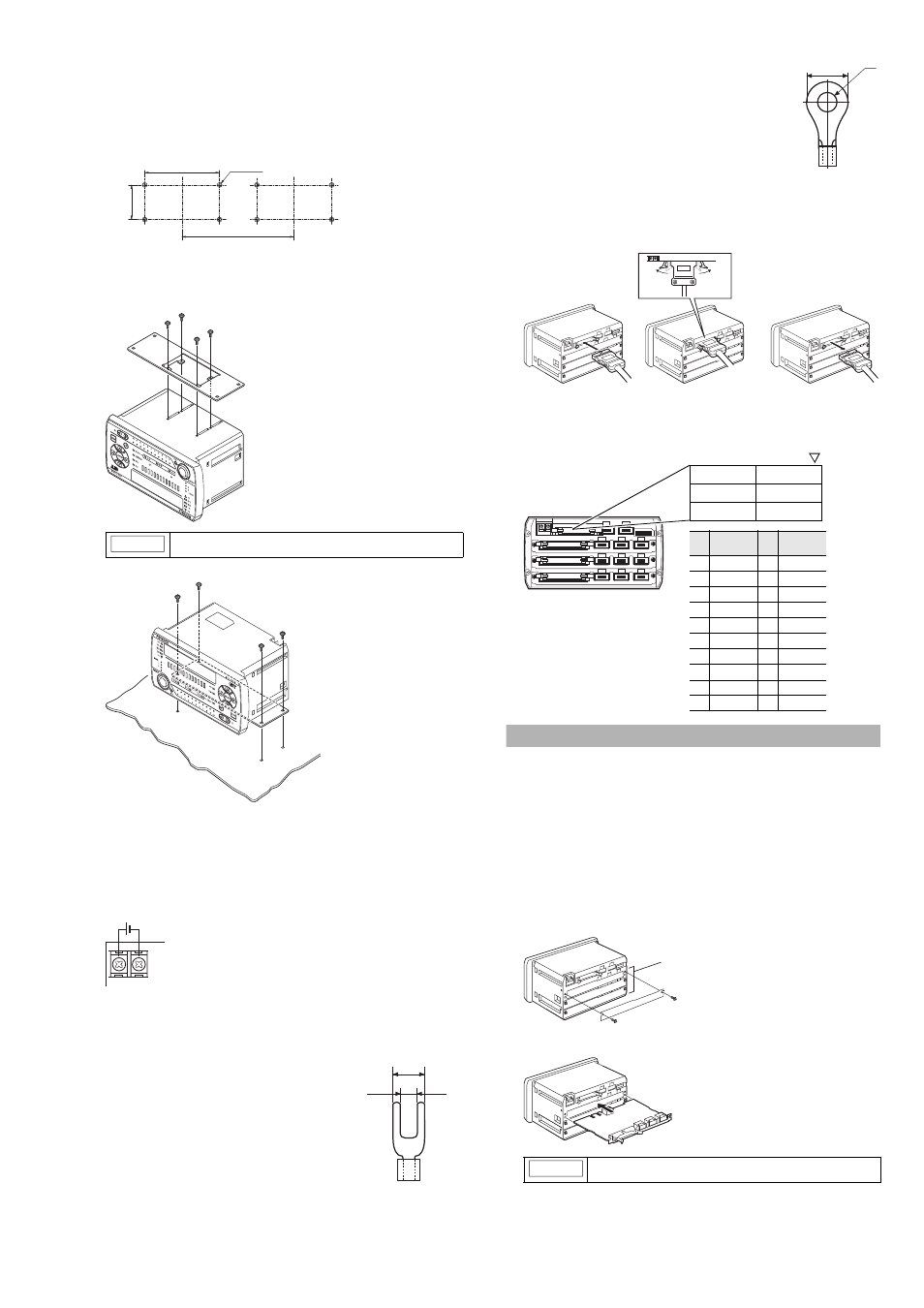
● Mounting on a table
When mounting the amplifier on a table, use the large amplifier
mounting bracket (OP-84331).
1
Create on a table opening for mounting referring to the
dimensions below.
2
Attach the large amplifier mounting bracket (OP-84331) on the
amplifier.
Use the four tapping screws supplied with the large amplifier to attach the
mounting bracket.
3
Secure the amplifier with M4 screws.
■
Connecting the power supply
● Applicable wire
For the wire for the power supply, use the wire that meets the
following specifications for the power supply wire.
Wire size
: AWG26 to16
Cross-sectional area
: 0.2 to 1.65 mm
2
● Crimp-type terminal
The power supply terminal of the amplifier uses M3 screws.
Use the Y or round terminal in the following size
Y terminal
Applicable dimension
B: Outer size of Y area
6 mm max.
d: Width of inner Y area
3.2 mm min.
(joint area with screw)
Round terminal
Applicable dimension
B: Outer size of round area
6 mm max.
d: Diameter of inner round area
3.2 mm min.
(joint area with screw)
■
Connecting the I/O connector
For the input and output of the GT2-100N/100P, use OP-22185 (MIL socket
connector 20-pin) sold separately.
For the information on how to assemble the connector and how to connect
the power cable, refer to "GT2-100 Series User's Manual".
● Pin arrangement of I/O connector
Refer to page 15 of this manual for details about I/O circuits.
Connecting Three or More Heads
• Two heads can be connected to the amplifier unit (GT2-100N/100P)
as standard.
• When adding three or more heads, use the optional head expansion
board (GT2-E3N/E3P) sold separately to the rear of the amplifier.
• Three heads can be added to one head expansion board. Up to
three head expansion boards can be added. So the maximum of
eleven heads can be added.
■
Mounting the head expansion board
1
Detach the head expansion board connection slot cover at the
rear of the amplifier.
The cover is fixed with the M3 screws (2 pieces).
2
Insert the head expansion board along the guide rail.
NOTICE
Apply tightening torque between 0.8 and 1.0 N•m.
40
150
163 min.
4-M4 tap
(unit: mm)
Secure with the included four screws.
DC20-30V
B
d
NOTICE
Make sure the head expansion board is fully seated.
B
φd
(When connecting the I/O connector)
(When disconnecting the I/O connector)
19 17 15 13 11 9 7 5 3 1
20 18 16 14 12 10 8 6 4 2
ID:1
ID:0
Pin
No.
Signal name
Pin
No.
Signal name
1 HIGH output
11 HIGH output
2 LOW output
12 LOW output
3 GO output
13 GO output
4 HH output
14 HH output
5 LL output
15 LL output
6 PRESET input 16 PRESET input
7 BANK A input 17 BANK A input
8 BANK B input 18 BANK B input
9 RESET input
19 RESET input
10 TIMING input 20 TIMING input
Head expansion board connection slot
1 to 3