Specifications, Sensor head, Box type – KEYENCE GT2-100 Series User Manual
Page 14: Air cylinder type, Gt2-100-m-e
14
GT2-100-M-E
Specifications
■
Sensor head
GT2-P***/PA*** cannot be connected to amplifier units purchased before April 15th 2014.
● Pencil type (GT2-PA12K/PA12 are air cylinder types)
*1
When the surrounding temperature is 20°C.
*2
This is a typical value at the center of the measuring range. The measuring force varies depending on the mounted condition of the dust boot.
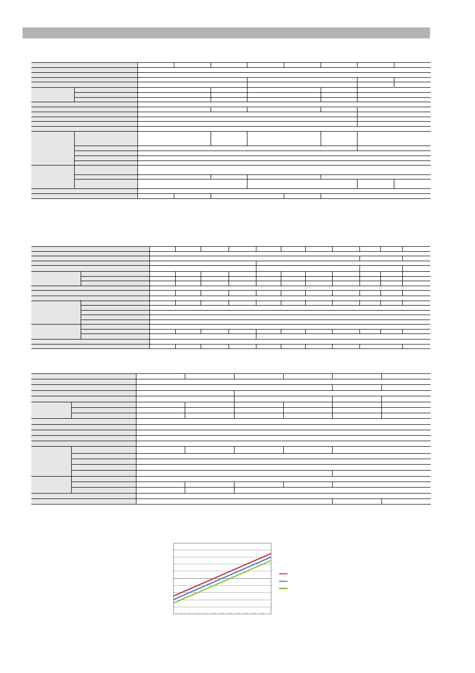
For GT2-PA12K/PA12, this is a representative value when using 0.25 MPa. The measuring force varies depending on the air pressure used. See table 1 for more details.
There is no dust boot for GT2-PA12K/PA12.
*3
When using an M8 oil resistant cable (GT2-CHP2M/5M/10M) as the sensor head cable.
*4
The contact is a separately sold option.
*5
Including the relay connector.
Note: Cannot be used with amplifier units purchased before April 15th, 2014.
● Box type
*1
When the surrounding temperature is 20°C.
*2
This is a typical value at the center of the measuring range. The measuring force varies depending on the mounted condition of the dust boot.
*3
The contact is a separately sold option.
● Air cylinder type
*1
When the surrounding temperature is 20°C.
*2
This is a typical value at the center of the measuring range. The measuring force varies depending on the mounted condition of the dust boot.
*3
Connect an air tube to the exhaust valve so that no foreign materials enter from the valve.
*4
When using mounting bracket D (OP-84327) with GT2-A32/A50, vibration is 0.75 mm.
*5
The contact is a separately sold option.
Model
GT2-P12K
GT2-P12KF
GT2-P12KL
GT2-P12
GT2-P12F
GT2-P12L
GT2-PA12K
GT2-PA12
Detection system
Scale shot system II Absolute type (without tracking error)
Measuring range
12 mm
Resolution
0.1 µm
0.5 µm
0.1 µm
0.5 µm
Indication accuracy
*1
1 µm (P-P)
2 µm (P-P)
1 µm (P-P)
2 µm (P-P)
Measuring force
*2
When installed facing down
1.0 N
0.2 N
1.0 N
0.2 N
1.2 N
When installed sideways
0.95 N
0.15 N
0.95 N
0.15 N
1.15 N
When installed facing up
0.9 N
0.1 N
0.9 N
0.1 N
1.1 N
Sampling interval
4 ms
Mechanical response
*1
10 Hz
4 Hz
10 Hz
4 Hz
-
Pressure range
-
0.24 to 0.26 MPa
Max. pressure
-
0.5 MPa
Fluid to use
-
Clean dry air
Operation indicator
2-color LED (red, green)
Environmental
resistance
Enclosure rating
IP67G (JIS)
*3
IP67 (IEC)
NEMA Type 13
*3
-
IP67G (JIS)
*3
IP67 (IEC)
NEMA Type 13
*3
-
IP67(IEC)
Surrounding air temperature
-10 to +55°C (No freezing)
0 to +55°C (No freezing)
Relative humidity
35 to 85% RH (No condensation)
Vibration resistance
10 to 55 Hz, Compound amplitude 1.5 mm, 2 hours each in X, Y, and Z axis
Shock resistance
1000 m/s
2
(IEC60068-2-27)
Material
Main unit
Main unit cover: SUS303, Spindle for GT2-PA12K/PA12: SUS430 (Fluorine-based coating), Indicator: PET, Sensor head - Connection cable: PUR, Connector: PBT,
Dust seal (GT2-PA12K/PA12 only): SUS303/SU304/aluminium (alumite treated)/special polyester fiber
Dust boot
NBR
-
NBR
-
Contact point
*4
SUS304, tungsten carbide
SUS304, SUS440C
SUS304,
tungsten carbide
SUS304,
SUS440C
Head cable
Sold separately (connected to relay connector)
Weight (excluding cable)
*5
Approx. 35 g
Approx. 45 g
Approx. 35 g
Approx. 45 g
Approx. 35 g
Model
GT2-H12K
GT2-H12KL
GT2-H12KF
GT2-H12KLF
GT2-H12
GT2-H12L
GT2-H12F
GT2-H12LF
GT2-H32
GT2-H32L
GT2-H50
Detection system
Scale shot system II Absolute type (without tracking error)
Measuring range
12 mm
32 mm
50 mm
Resolution
0.1 µm
0.5 µm
Indication accuracy
*1
1 µm (P-P)
2 µm (P-P)
3 µm (P-P)
3.5 µm (P-P)
Measuring force
*2
When installed facing down
1.0 N
0.4 N
1.0 N
0.4 N
1.0 N
0.4 N
1.0 N
0.4 N
2.1 N
1.2 N
3.2 N
When installed sideways
0.9 N
0.3 N
0.9 N
0.3 N
0.9 N
0.3 N
0.9 N
0.3 N
1.8 N
0.9 N
2.8 N
When installed facing up
0.8 N
0.2 N
0.8 N
0.2 N
0.8 N
0.2 N
0.8 N
0.2 N
1.5 N
0.6 N
2.4 N
Sampling interval
1 ms
Mechanical response
*1
10 Hz
4 Hz
10 Hz
4 Hz
10 Hz
4 Hz
10 Hz
4 Hz
6 Hz
5 Hz
7 Hz
Operation indicator
2-color LED (red, green)
Environmental
resistance
Enclosure rating
IP67
-
IP67
-
IP67
-
IP67
-
IP67
-
IP67
Surrounding air temperature
-10 to +55°C (No freezing)
Relative humidity
35 to 85% RH (No condensation)
Vibration resistance
10 to 55 Hz, Compound amplitude 1.5 mm, 2 hours each in X, Y, and Z axis
Shock resistance
1000 m/s
2
(IEC60068-2-27)
Material
Main unit
Main unit cover: zinc die-cast, Indicator: polyarylate (PAR)
Dust boot
NBR
-
NBR
-
NBR
-
NBR
-
NBR
-
NBR
Contact point
*3
SUS304, tungsten carbide
SUS304, SUS440C
Cable
Sold separately (connected to M8 connector)
Weight (excluding cable)
Approx. 95 g Approx. 95 g Approx. 100 g Approx. 100 g Approx. 95 g Approx. 95 g Approx. 100 g Approx. 100 g
Approx. 270 g
Approx. 320 g
Model
GT2-A12K
GT2-A12KL
GT2-A12
GT2-A12L
GT2-A32
GT2-A50
Detection system
Scale shot system II Absolute type (without tracking error)
Measuring range
12 mm
32 mm
50 mm
Resolution
0.1 µm
0.5 µm
Indication accuracy
*1
1 µm (P-P)
2 µm (P-P)
3 µm (P-P)
3.5 µm (P-P)
Measuring force
*2
When installed facing down
1.2 N
0.4 N
1.2 N
0.4 N
2.1 N
3.2 N
When installed sideways
1.1 N
0.3 N
1.1 N
0.3 N
1.8 N
2.8 N
When installed facing up
1.0 N
0.2 N
1.0 N
0.2 N
1.5 N
2.4 N
Sampling interval
1 ms
Operation indicator
2-color LED (red, green)
Pressure range
0.25 to 0.5 MPa
Max. pressure
1.0 MPa
Fluid to use
Dry air
Environmental
resistance
Enclosure rating
IP67
*3
-
IP67
*3
-
IP67
*3
Surrounding air temperature
0 to +55°C (No freezing)
Relative humidity
35 to 85% RH (No condensation)
Vibration
*4
10 to 55 Hz, Compound amplitude 1.5 mm, 2 hours each in X, Y, and Z axis
Shock resistance
1000 m/s
2
(IEC60068-2-27)
-
Material
Main unit
Main unit cover: zinc die-cast, Cylinder: aluminum alloy, Air coupling socket (resin part): polyacetal, Air coupling socket (metal part): nickel plated brass, Indicator: polyarylate (PAR)
Dust boot
FKM
-
NBR
-
NBR
Contact point
*5
SUS304, tungsten carbide
SUS304, SUS440C
SUS304, SUS440C
Sensor head cable
Sold separately (connected to M8 connector)
Weight (excluding sensor head cable)
Approx. 145 g
Approx. 340 g
Approx. 405 g
0
1
2
3
4
5
6
7
8
9
10
11
12
Measuring force (N)
Spindle retracted
Spindle extended
Table 1. Relationship between spindle position and measuring force grouped according to used air pressure.
(When installing side mounting, the measuring force is -0.05 N. When installing upward mounting, the measuring force is -0.1 N.)
Spindle position (mm)
Applied pressure (MPa)
1.7
1.2
0.26 MPa
0.25 MPa
0.24 MPa
0.7