Toggling the display, End program), E lv-s-im ■ when using the lv-s31 – KEYENCE LV-SB User Manual
Page 9: When using a model other than lv-s31, When using the lv-s31
9
E LV-S-IM
■ When using the LV-S31
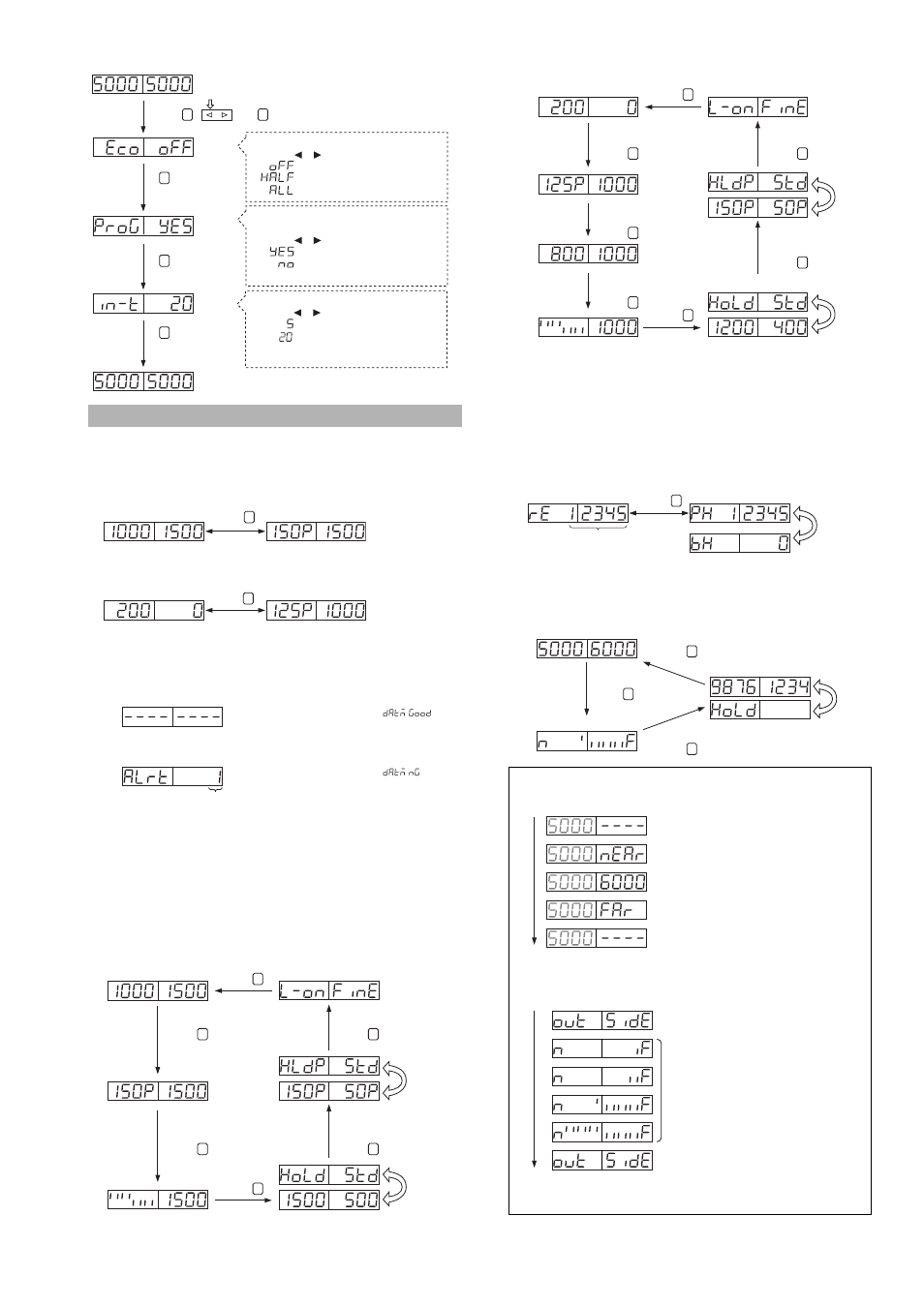
Toggling the Display
■ When using a model other than LV-S31
• When "duAl" is selected for the number of digits of light intensity dis-
play and "Std" is selected for display mode
* The displayed number indicates the following type of alarm.
For more information about remedies to errors, see "Error indication" on page 10.
1: Over DSC correction limit
2: DSC small fluctuation detection
3: Invalid DSC EEPROM contents
4: Over fluctuation width during zero datum calibration
5: DSC speed limit alarm
• When "duAl" is selected for the number of digits of light intensity dis-
play and "FuLL" is selected for display mode
*1
The received light intensity is displayed in percentage with reference to
the setting value.
*2
Its stability is indicated between 85 to 115 %. The number is varied by
the unit of 5 %.
*3 The peak- and bottom-hold values since the power-on are displayed.
The hold values can be reset by pressing the manual button.
• When "rE" is selected for the number of digits of light intensity display
■ When using the LV-S31
Selecting the shift function input time
Press the or button to select.
• 5ms
• 20ms
The input time is fixed to 20 ms for all other
functions.
Selecting the memory of value set by an
external input while using the shift function
Press the or button to select.
• Saves the value *1
• Does not save the value (clears data at power-off)
*1 Data can be saved up to one million times.
MODE
MODE
MODE
Selecting the Power saving function (Eco mode)
Press the or button to select.
• Normal use
• Eco-half
• Eco-all
Press , , and for three seconds or more at the same time.
MODE
SET
(End Program)
(The display shown to the left appears after " " is
displayed during zero datum calibration)
When zero datum calibration is completed without errors
(The display shown to the left appears after " " is
displayed during zero datum calibration)
When zero datum calibration is completed with errors
Alarm contents*
When "Auto" is selected for the operation of control output 2 and
the channel setting is switched to "2"
When zero datum calibration is not selected
Setting value Current value
Margin
Current value
Press
MODE
When zero datum calibration is selected
Press
MODE
Setting value Current value
after zero datum
calibration
Margin
Current value
before zero datum
calibration
When zero datum calibration is selected
Setting value
Current value
Margin*
1
Current value
Bar display*
2
Current value
Output status
Power mode
Peak value
margin
Bottom value
margin*
3
Peak value
Bottom value*
3
Flashes
alternately
Flashes
alternately
Press
MODE
Press
MODE
Press
MODE
Press
MODE
Press
MODE
Press
MODE
When zero datum calibration is selected
Current value after
zero datum calibration
Current value after
zero datum calibration
Margin*
1
Current value before
zero datum calibration
Bar display*
2
Current value after
zero datum calibration
Output status
Power mode
Peak value
margin
Bottom value
margin*
3
Peak value before
zero datum calibration
Bottom value before
zero datum calibration
Flashes
alternately
Flashes
alternately
Press
MODE
Press
MODE
Press
MODE
Press
MODE
Press
MODE
Press
MODE
Current value before
zero datum calibration
Current value before
zero datum calibration
Press
MODE
Current value
Press
MODE
Peak-hold value
Bottom-hold value
Flashes
alternately
Setting value Current value
Peak value
Bottom value
Position display
Flashes
alternately
Press
MODE
Press
MODE
Press
MODE
Digital display (The position of the target from the center position
[5000] is displayed in number.)
Outside of the detection range
The workpiece is near the sensor with reference
to the digital display range.
With 5000 being the middle, the value
increases as the distance from the sensor increases.
The workpiece is far from the sensor with reference to
the digital display range.
Outside of the detection range
Position display (The position of the target with reference to the
center position is displayed.)
Outside of the detection range
Outside of the detection range
The number of bars increases as the distance from
the sensor increases, taking the state of "A" as the
center.
When adjusting the center position with the trimmer
on the sensor head, adjust it to the state of "A".
A
(1)
(2)
(1)
(2)
(3) The peak/bottom hold value since the power is turned on is displayed.
Pressing the Manual button can reset the hold value.
(3)