Fine-adjusting sensitivity, Area detection mode – KEYENCE LV-SB User Manual
Page 5
5
E LV-S-IM
Note
•
The zero datum calibration cannot be used when bank selection (bAnk) is
set for the control input function.
•
The zero datum calibration can only be used with Output 1.
•
When zero datum calibration is performed on models other than LV-S41/
S41L, the DSC function is turned on.
•
When zero datum calibration is performed on LV-S41/S41L, the DSC func-
tion is turned off.
•
After zero datum calibration is performed, the minus sign will not be dis-
played. In situations when the minus sign is supposed to be displayed, the
display stay as zero.
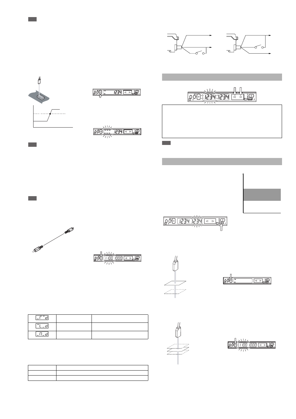
■ Positioning calibration (not available for the LV-S31)
1
Press the SET button quickly
without a workpiece being placed.
2
Place a workpiece on the position
where you want to perform positioning.
3
Press the SET button for at least
three seconds. When the indication
flashes, release the button.
Note
•
Output 2 for Bank A and Outputs 1 or 2 for Bank B can be used.
•
When the control input function is set to bank select (bAnk), Output 1 on
Bank A can be used.
■ % calibration (not available for the LV-S31)
This is a calibration method that can set the setting value by percentage with
reference to the received light intensity at the time of sensitivity setting. For
example, if the target value is set to –10P, the setting value is determined 10%
lower than the received light intensity when the SET button is pressed.
By regularly performing external calibration from the device such as a PLC,
even a little sensitivity difference can be steadily detected.
Note
The % calibration function cannot be used when the DSC function is turned
on or the zero datum calibration is being used.
1
When selecting the sensitivity
setting method (page 7, No. 5),
select the % calibration, and set
the target value of calibration.
(The value can be set by 1%.)
2
Taking the desired light intensity as
a reference (normally without a
workpiece), press the SET button.
* While the % calibration is in use, other calibrations (sensitivity setting) can-
not be used.
* The setting value is calculated based on the intermediate value between
MAX. and MIN. of the received light intensity while the SET button is being
pressed. The conditions in acquiring the sampling value can be changed
using the procedure to set the special modes.
■ Edge detection (not available for the LV-S31)
Detects the change in the received light intensity during a given period of time.
In the detection mode (page 7, No. 4), select the following edge detection
mode and the detection time.
Sensitivity setting
The sensitivity is set to maximum when the SET button is pressed once.
(If the SET button is pressed and held for a while, changes in the light intensity dur-
ing that period are ignored.)
Output status
■ External calibration
1
Select the external calibration with the menu switch.
2
Short-circuiting the pink wire 20 ms or more as follows for each model is
equivalent to pressing the SET button.
* LV-11SB/11SBP only
* The maximum number of times of writing is one million.
* Input is not accepted while setting any mode (page 7).
Fine-adjusting Sensitivity
The setting value can be directly changed by pressing the manual button.
Note
When DSC and zero datum are activated, perform fine-adjustment without a
workpiece.
Area Detection Mode
This mode is suited to detecting the received light intensity only of a certain range.
To set this mode, select the area
detection mode among the
detection modes. (page 7, No. 4,
or page 8 No. 5)
The display of the setting values
of the upper and lower limits can
be switched with the channel
selection switch.
Keep the range of setting value 1 > setting value 2.
Nothing is detected when setting value 1
≤ setting value 2.
Output 2 cannot be used while the area detection mode is in use.
■ Sensitivity setting method 1 (Normal sensitivity)
1
Place a workpiece on the upper
limit of the received light intensity
that you want the sensor to detect,
and press the SET button once.
2
Place a workpiece on the lower limit
of the received light intensity that
you want the sensor to detect, and
press the SET button once again.
If the sensitivity difference does not have enough room, “+++” flashes after
the calibration is finished. The setting value is changed at this time, too.
■ Sensitivity setting method 2 (when % calibration is selected)
1
Place a workpiece on the
designated position, and press the
SET button once.
Specify the setting values to the
upper and lower limits of the time
when you press the SET button.
Example: When the setting value of the % calibration is set to 10P
The value that is the received light intensity when the SET button is pressed
plus 10% is set for the setting value 1, and minus 10% for the setting value 2.
■ Bank function
Normally, up to two setting values can be set, but by using the bank function,
up to four setting values can be set.
Rising detection
Detects the increase (rising edge) of
the received light intensity
Falling detection
Detects the decrease (falling edge) of
the received light intensity
Rising/falling
(both-edge) detection
Detects both the rising and falling
edges of the received light intensity.
Setting
Operation
L-ON
Always OFF. Turns ON only when the light intensity changes.
D-ON
Always ON. Turns OFF only when the light intensity changes.
Received light intensity
Setting value
Time
The sensitivity is set at the point where the value
becomes ON exactly when a workpiece comes
to the point where you want to position it.
When “five-digit display” is set (page 7, No.11) for the number of dig-
its to be displayed for the received light intensity
1
Press the manual button quickly once, and check that the setting value flashes.
2
While the setting value is flashing, change the setting value with the
Manual button.
Brown*
Blue*
Pink
Brown*
Pink
Blue*
+V
0 V
+V
0 V
LV-11SB/12SB
LV-11SBP/12SBP
Setting value 1
(Upper limit)
Setting value 2
(Lower limit)
ON
OFF
OFF
Received light intensity
1: Setting value upper limit
2: Setting value lower limit
1: Upper limit
2: Lower limit