Interference protection function, Keylock, Power-save (eco mode) – KEYENCE LV-SB User Manual
Page 10: Caution on a lustrous workpiece (lvs31), Error indication
10
E LV-S-IM
Interference Protection Function
The LV-S Series can prevent mutual interference by connecting amplifier units.
■ When using a model other than LV-S31
■ When using the LV-S31
Keylock
You can lock the operation buttons to prevent the settings from being
changed by careless operation of the buttons.
Setting operations for sensitivity or modes are disabled during keylock, but
the display can be switched.
•
The same steps can be taken to deactivate keylock.
Power-save (Eco Mode)
The numerical display disappears, and the current consumption is reduced.
If a key operation is performed during the Eco mode, the display returns to
normal. If no more key operation is performed for 4 seconds, the display
returns to the Eco mode.
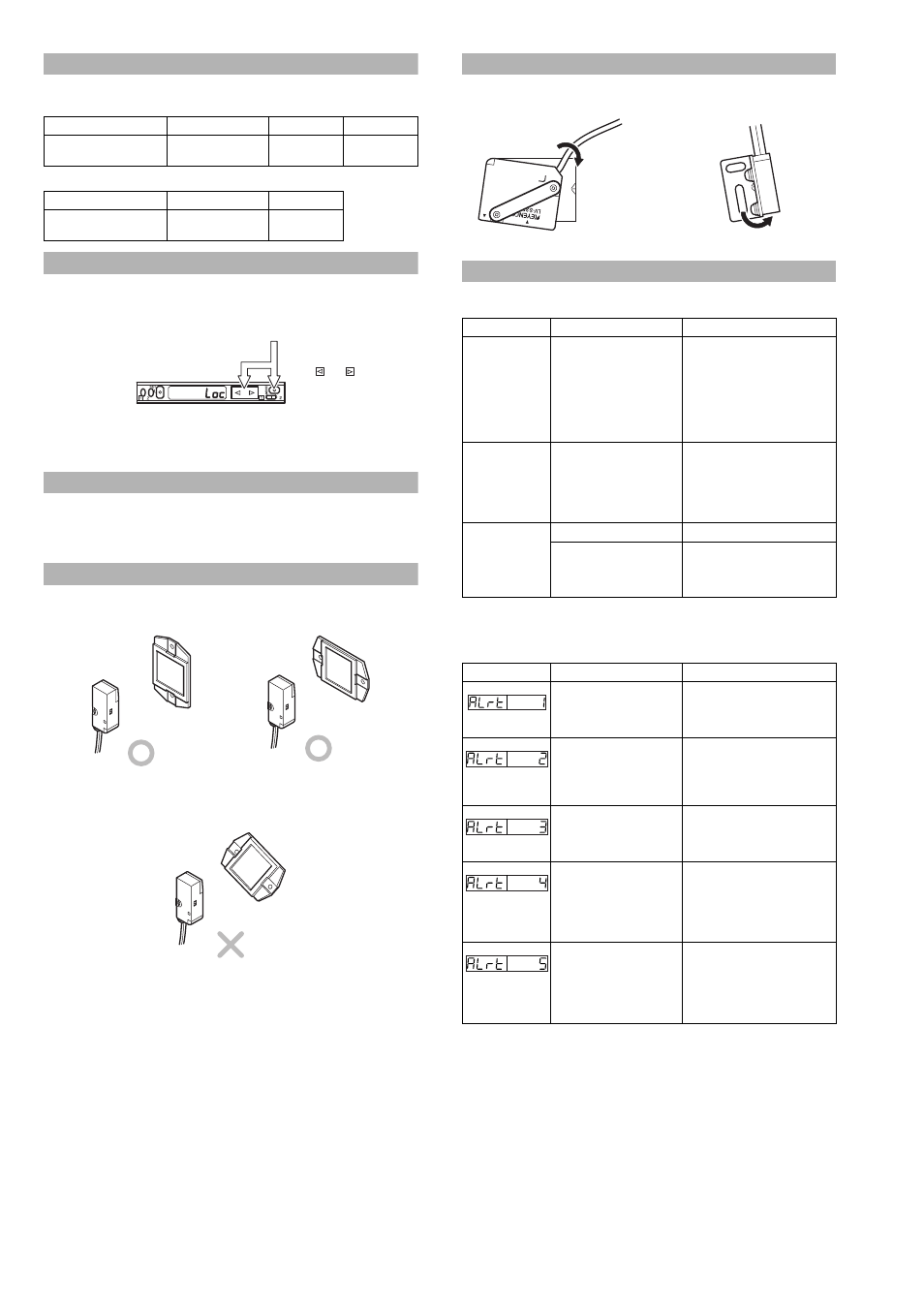
Cautions on Installing the Reflector (LV-S61/S62/S63)
Be sure to install the reflector so that it is vertical or horizontal against the sen-
sor unit.
If the reflector is installed diagonally against the sensor unit, the received light
intensity will decrease significantly.
Caution on a lustrous workpiece (LVS31)
If the workpiece is lustrous, the trimmer adjustment may not succeed or
detection may be unstable. In such a case, install the sensor slightly tilted.
Error Indication
The following indications on the LCD display show the error events. Correct
the problem using the following countermeasures.
The following table shows the alarms when "Auto" is selected for the operation
of control output "2"and channel setting is switched to "2". Refer to the follow-
ing table to remedy the alarms.
Power mode
HSP (HIGH SPEED)
FINE/TURBO
SUPER/ULTRA
Number of units required to
prevent interference
Unavailable
2 units
4 units
Power mode
HSP (HIGH SPEED)
STD
Number of units required to
prevent interference
2 units
4 units
While pressing the
MODE button, press
the
or
button for
at least three seconds.
The indicator shows that key-
lock is activated.
Error indication
Cause
Remedy
ErH
Sensor head is not
connected.
Head cable is broken.
•
Check that the sensor head is
connected.
•
Check that the head cable is
not broken.
•
Check the connection of the
head cable to the connector.
•
After checking these points,
turn on the power again.
ErC
Overcurrent flows through
the output wire.
•
Check the load and reduce
the current to be within the
rated range.
•
Check that the output wire
does not touch another wire or
a frame.
ErE
Data write/read error
•
Perform initialization.
Data has been written in
the EEPROM more than
one million times and can
no longer be updated.
•
If you need to write more data,
replace the amplifier unit.
Display
Alarm contents
Remedy
Over DSC correction limit:
Received light intensity
during OFF exceeds the
DSC correction limit.
Change the setup conditions or
replace the sensor, and secure
the correct received light
intensity during OFF.
DSC small fluctuation
detection:
There are fluctuations
within the range for the
alarm output level (rtio).
Move the workpiece to the
correct position.
Invalid DSC EEPROM
contents:
Failed to write data to
EEPROM.
Restart the power or initialize.
Over fluctuation width during
zero datum calibration:
The fluctuations of
received light intensity
during calibration are too
large.
Take anti-vibration measures in
order to suppress fluctuations
during calibration.
DSC speed limit alarm:
The received light intensity
fluctuated a large amount
in a short period of time.
•
Move the workpiece to the
correct position.
•
Take anti-vibration measures
in order to suppress
fluctuations in the received
light intensity.