How to set up each mode (models other than lv-s31), End program, E lv-s-im – KEYENCE LV-SB User Manual
Page 7: B8 7 6 5
7
E LV-S-IM
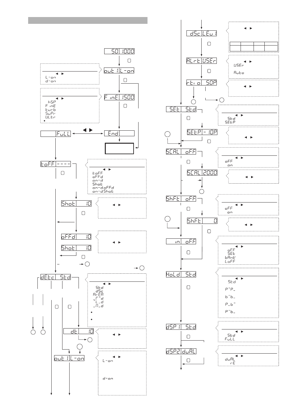
How to Set up Each Mode (Models other than LV-S31)
The settings of Output 1 and 2 can be divided into common settings and indi-
vidual settings depending on the modes. Change the mode by using the
channel selection switch. To exit the mode setting while it is not completely
finished, press the MODE button for over 2 seconds. Refer to page 8 when
using the LV-S31.
A
b
a
OR
When Output 2 is
set, Alarm output is
selected, and
"Auto" is selected
When Timer
OFF
is selected
When other
setting than
Timer OFF
is selected
When Output 1 is set
and zero datum
calibration is selected
When a mode
Normal or
Area detection
is selected.
When a mode
DSC is
selected.
When a mode other
than Normal, DSC,
or Area detection
is selected
(If the sensor head is “LV-S41/S41L” )
A
B
B
* Cannot be selected when LV-S62/S63 is being used.
When Output 2
is set.
When zero
datum calibration
is selected for
Output 1
B
When a mode DSC is
selected for Output 1
and a mode Normal is
selected for Output 2
C
End of the basic
menu display
When selecting a timer mode,
If other setting than *1 is selected
→ a
If *1 is selected
→ b
1
Selecting output
2
3
Selecting the Timer mode
4
Selecting the detection mode
Selecting the detection operation
Press the or button to select.
• L-on Mainly for reflective type
[light intensity with workpiece >
light intensity without workpiece]
(The output is on when the light
enters)
• d-on Mainly for thrubeam type
[light intensity with workpiece <
light intensity without workpiece]
(The output is on when the light
is blocked.)
Output 1/2 individual setting
Output 1/2 common
Output 1/2 individual setting
Selecting the power mode (response time)
Press the or button to select.
• Timer OFF
• OFF delay
• ON delay
• One-shot
• ON delay, OFF delay *1
• ON delay, one-shot *1
Output 1/2 individual setting*
Press the or button to select.
• Normal (light intensity) mode
• Area detection mode
• Area detection mode
• Detects the rising edge of the received light intensity.
• Detects the falling edge of the received light intensity.
• Detects both the rising and falling edges
of the received light intensity
The % calibration function cannot be used when the
DSC function is turned on or the zero datum
calibration is being used.
The shift function cannot be used when the DSC
function is turned on or the zero datum calibration is
being used.
Timer setting
Press the or button to select.
Can be set between 0.1 and 5000 ms.
When *1 is selected, the ON delay
timer is activated.
Timer setting 2
Sets an OFF delay (one-shot) time.
Press the or button to select.
Can be set between 0.1 and
5000 ms.
Selecting the derivation time
Press the or button to select.
The time can be selected from 0.25/0.5/1/2.5/
5/10/25/50/100 ms. (The available times vary
depending on the power mode.)
When the power mode is changed, redo the calibration.
Press for two seconds
or more
MODE
Press the or button to select.
• Turns ON while the light enters.
• Turns ON while the light is shielded.
Press the or button to select.
• HIGH SPEED:80 µs
• FINE:250s
• TURBO:500s
• SUPER:2 ms
• ULTRA:4 ms
MODE
MODE
MODE
MODE
MODE
MODE
MODE
C
C
End program
When %
calibration
is selected
When zero datum
calibration are selected
When zero datum
calibration or % or
DSC
calibration is selected
When OFF
is selected
When ON is
selected
When OFF
is selected
When ON is
selected
When DSC mode,
display scaling,
or zero datum
calibration are
selected
B
B
B
8
7
6
5
Selecting the sensitivity selecting method
Setting the display scaling
Setting the shift function
Selecting the control input function
Press the or button to select.
• Updates the peak/bottom value every time that the
current light intensity is less than or more than the set value
• Displays the maximum and minimum peak values
since the power was turned on (total number)
• Displays the maximum and minimum bottom values
since the power was turned on (total number)
• Displays the minimum peak value and the maximum
bottom value since the power was turned on (total number).
• Displays the maximum peak value and the minimum bottom
value since the power was turned on (total number).
9
Selecting the hold function
11
Selecting the number of digits of light intensity display
Press the or button to select.
• Normal screen display mode
• Full screen display mode
10
Selecting the display mode
Selecting the correction speed
Press the or button to select.
The correction is made faster as
the number becomes larger (1 to 3).
(Select 1 for normal cases.)
Selecting the operation for control output 2
Press the or button to select.
• Uses normal operations for
control output 2.
• Uses alarm output for control
output 2.
Setting the range for alarm output level
Press the or button to select.
Set in the range between 0 and 100P.
* Normally use the setting at 50%.
Mode LEv1 LEv2 LEv3
Correction 104.86s
1.64s
25.6ms
speed
Output 1/2 common
Press the or button to select.
• Normal sensitivity setting
• % calibration
Output 1/2 common
Output 1/2 common
Output 1/2 common
Output 1/2 common
Output 1/2 common
Output 1/2 common
Setting the display scaling target value
Press the or button to select.
It can be set by the unit of 100.
Setting the shift target value
Press the or button to select.
It can be set by the unit of 1.
Setting the target value of the %
calibration
Press the or button to select.
From –99% to +99% can be set.
Press the or button to select.
• Normal display
• Display scaling
Press the or button to select.
• Do not use shift
• Use shift
Press the or button to select.
• Does not use the control input
• External calibration
• Bank selection
• Laser emission stop
Press the or button to select.
• Four-digit display (the setting value is also displayed)
• Five-digit display
MODE
MODE
MODE
MODE
MODE
MODE
MODE
MODE
MODE
MODE
MODE
* When Area detection mode is selected in "4.Selecting the detection mode", "----" is displayed in
the Output 2 setting and Output 2 cannot be selected.
If a mode other than the Normal/Dsct Area detection mode is selected for either Output 1 or 2, the
setting of item 5 or 6 or 7 cannot be selected for both Output 1 and 2.