Dsc (dynamic stability control), Shift function, Hold function – KEYENCE LV-SB User Manual
Page 6
6
E LV-S-IM
Note
The zero datum calibration cannot be used when using the bank function.
1
When selecting the control input function (page 7, No.8, or page 8, No. 7),
select the bank selection.
2
Normal bank A becomes bank B when the external input wire (pink wire)
is short-circuited.
* LV-11SB/11SBP only
Set or change the bank B while the input signal is input.
Setting the Display Scaling (not available for the LV-S31)
This is the function to adjust the received light intensity during operation to the
“scaling target value”.
Note
This function cannot be used when zero datum calibration is being used.
1
When setting a display scaling (page 7, No. 6), select to use the display
scaling, and set the target value. (The explanation here deals with the case
where the target value is set to 2000.)
2
During the normal display, press the SET button while pressing the MODE button.
The display changes as follows, and the target value (which is 2000) to be
set as a scale is displayed.
↓
The display scaling is performed.
The reference light intensity can be set in the following range in reference with
the currently received light intensity:
Special function
After an external calibration, the scaling can be externally performed by
inputting the signal again in three seconds.
•
In the case of the % calibration (example)
* Input is not accepted while setting any mode. (page 7)
DSC (Dynamic Stability Control)
DSC automatically corrects the setting value according to the changes in the
received light intensity when there is no workpiece (output OFF).
This function is effective when the light intensity difference is small when
judging whether or not there is a workpiece. At Detection mode selection
(page 7, No.4), select "
".*
How to set the sensitivity is the same as in the normal mode.
* The value is stored in memory even after the power is turned off.
Note
•
When connected to a sensor head other than LV-S31/S41/S41L, the DSC func-
tion turns on automatically when the zero datum calibration is performed and
operates while turned on when there is blocked light. When other calibrations are
performed in this state, the DSC function is turned off.
•
When connected to LV-S41/S41L, the DSC function turns off when the zero datum
calibration is performed and operates while turned on when there is entered light.
■ Alarm output level (ALrt) setting
Specify the operation for control output 2 when the DSC function is set to ON.
■ Alarm output level (rtio) setting
Specify the level at which to output an alarm when the received light intensity
changes as moderately as the control output stays off (specifying the moder-
ate fluctuation alarm level).
DSC is not performed during a period when the received light intensity falls
below the alarm level.
Specified range: 0 to 100%
100%: The moderate fluctuation alarm is not output.
50%: An alarm is output when the received light intensity changes from the
background state up to half the setting value.
0%: An alarm is output when the received light intensity gets any closer to
the setting value from the background state.
Note
Normally use the setting at 50%. Smaller values can affect the response and
prevent the alarm from becoming cleared.
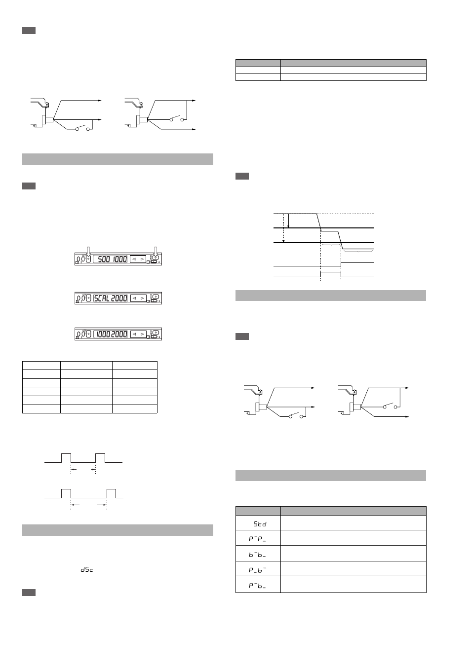
Timing chart
Shift Function
Forcibly synchronizes the received light intensity with the preset value (shift
target value). (Adds and subtracts the received light intensity.)
Regular synchronization inputs from a PLC or other device stabilizes the
detection of the target that has a little light intensity difference.
Note
The shift function cannot be used when the DSC function is turned on or the
zero datum calibration is being used.
1
When setting a shift function (page 7, No. 7, or page 8, No. 6), select to
activate the shift function, and set the shift target value.
* LV-11SB/11SBP only
* Whether or not to save the current display status changed by an external input
can be selected in the special mode (See “How to set the special mode” on
page 9). The default is to “Save”.
It is recommended that you set “Do not save” when the external input is fre-
quently performed. The maximum number of times of writing is one million.
Hold Function
This function holds the peak value and the bottom value of the received light
intensity during operation.
At Hold mode selection (page 7, No.9), select the hold mode.
Power mode
Minimum value
Maximum value
The error is indicated
when the value is out of
the range.
HSP
Approx. 1/20 times
Approx. 16 times
FINE
Approx. 1/40 times
Approx. 8 times
TURBO
Approx. 1/80 times
Approx. 4 times
SUPER
Approx. 1/160 times
Approx. 2 times
ULTRA
Approx. 1/320 times
Approx. 1 time
Brown*
Blue*
Pink
Brown*
Pink
Blue*
+V
0 V
+V
0 V
LV-11SB/12SB
LV-11SBP/12SBP
%calibration
Display scaling
Input ON
Input OFF
Within 3
seconds
%calibration
%calibration
Input ON
Input OFF
3 seconds
or more
Mode
Operation
Auto
Control output 2 acts as an alarm output.
uSEr
Control output 2 performs a usual operation.
Hold mode
Operation
Updates the peak and bottom values every time the current light
intensity exceeds or drops below the specified value.
Displays the maximum and minimum peak values since the
power is turned on (total number).
Displays the maximum and minimum bottom values since the
power is turned on (total number).
Displays the minimum peak value and the maximum bottom
value since the power is turned on (total number).
Displays the maximum peak value and the minimum bottom
value since the power is turned on (total number).
rtio
100%
Received light intensity
Alarm level
Alarm state
Workpiece detection
(no alarm)
Output 1 (Control output)
Output 2 (Alarm output)
Setting value
Received light intensity
Ex: When using a transmission or retro-reflective type
Brown*
Blue*
Pink
Brown*
Pink
Blue*
+V
0 V
+V
0 V
LV-11SB/12SB
LV-11SBP/12SBP