Mounting the amplifier unit, Input/output circuit schematic – KEYENCE LV-SB User Manual
Page 2
2
E LV-S-IM
■ LV-S41
■ LV-S61
■ LV-S62
■ LV-S63
■ LV-S71
The operation indicator works in conjunction with the Output selected at the
channel selection switch. (It does with Output 1 in area detection mode.)
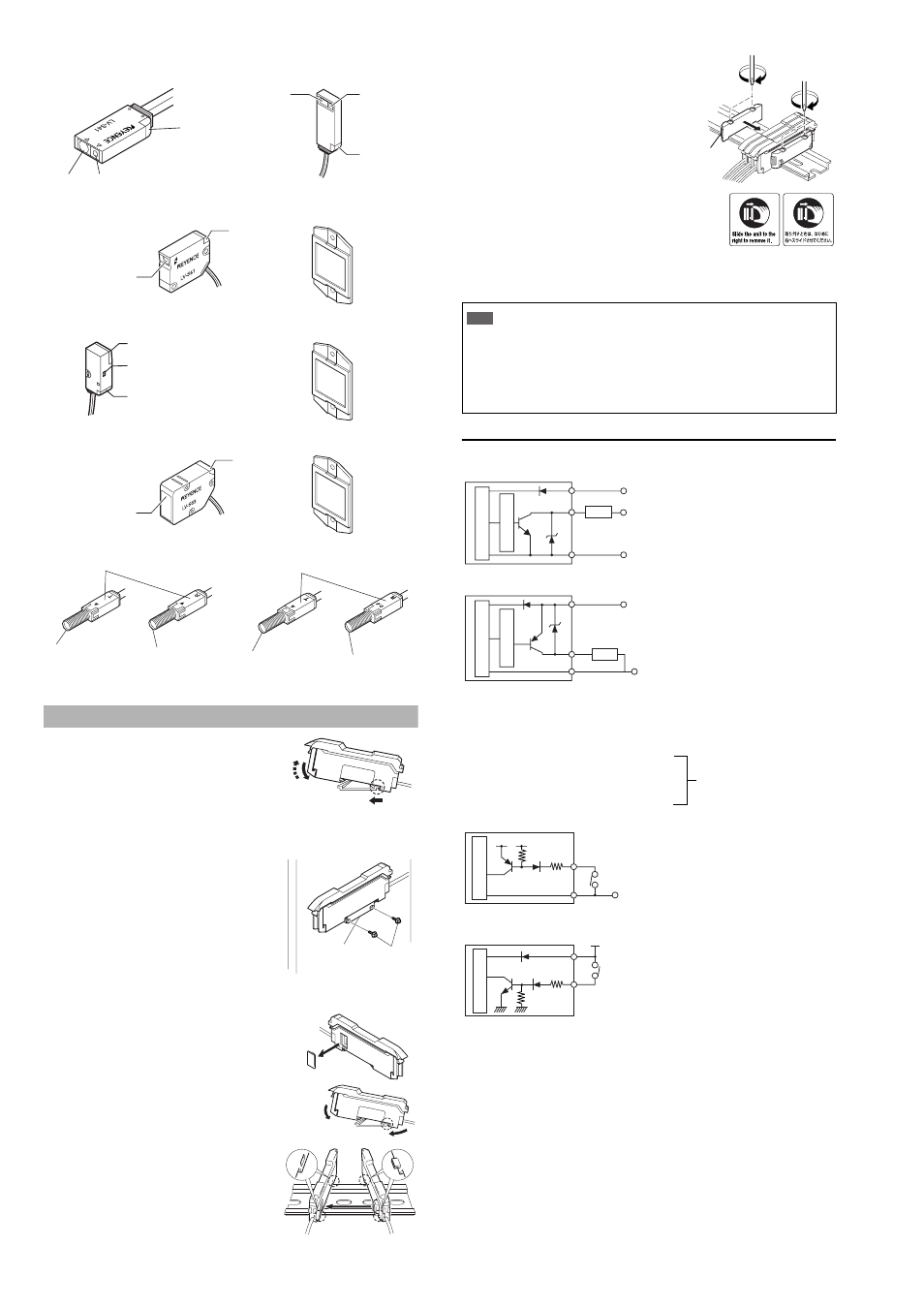
Mounting the Amplifier Unit
■ Mounting on a DIN rail
1) Align the claw at the bottom of the main body with the
DIN rail. While pushing the main body in the direction
of the arrow 1, slant it in the direction of the arrow 2.
2) To dismount the sensor, raise the main body
in the direction of the arrow 3 while pushing
the main body in the direction of the arrow 1.
■ Installation using the mounting bracket (accessory) (LV-11SB/11SBP only)
Mount the amplifier unit using the supplied
mounting bracket as shown in the figure.
■ Connecting several amplifier units
Up to 16 expansion units LV-12SB can be installed to the main unit LV-11SB.
1
Remove the protection cover on the side of the
main unit.
2
Install the amplifier one by one on the DIN rail.
3
Engage the two claws of the expansion
unit with the recesses on the main unit
side until you hear a click sound.
4
Install the end units on both ends of
the amplifier unit.
Fasten the screws on the top of the
end units (at two positions on both
end units) with the Philips screw-
driver.
* The stickers on the right are provided. Attach
the sticker on the place near the amplifier unit.
■ Removing the amplifier unit
1
Remove the end units.
2
Slide the expansion unit and remove it one by one.
Input/Output Circuit Schematic
■ Output circuit
LV-11SB/12SB (NPN output type)
LV-11SBP/12SBP (PNP output type)
The power of the expansion unit LV-12SB (P) is supplied by the Extension connec-
tor on the side of the main unit LV-11SB (P). The power wires (brown and blue) of
the main unit and those of the expansion unit are unified inside by the connector.
■ Input circuit
LV-11SB/12SB (NPN output type)
LV-11SBP/12SBP (PNP output type)
Receiving
section
Transmitting section
Operation
indicator
(red)
■ LV-S41L
Transmitting
section
Receiving
section
Operation
indicator
(red)
Transmitting section,
Receiving section
Operation
indicator (red)
Reflector (accessory)
Reflector (accessory)
Transmitting section,
Receiving section
Spot selection switch
Operation indicator
(red)
Transmitting section,
Receiving section
Operation
indicator (red)
Reflector (accessory)
Operation indicator (red)
Transmitting section
Receiving section
Transmitter
Receiver
■ LV-S72
Operation indicator (red)
Transmitting section
Receiving section
Transmitter
Receiver
(1)
(2)
(3)
M3 screw
Mounting bracket
(OP-25431)
(1)
(2)
Important
• When installing additional expansion unit, be sure to use the DIN rail and the end units.
• Turn off the power when installing or removing the unit.
• Do not remove the protective cover of the extension connector on the
amplifier expansion unit that is added at the end.
• Do not remove the amplifier unit with all added units attached, from the DIN rail.
• Verify the operation ambient temperature after additional installation. (“Specifications” page 11)
• Do not use full calibration functions or stability output when the expansion unit of
the LV-S Series is connected to a device with full calibration functions (such as
FST or PS-T) via external input. Doing so may lead to product malfunctions.
Two end units are
supplied with an
expansion unit.
OP-26751
DC5-40V
DC12-24V
Load
Black/white (control output 1/2)
Brown *
Blue *
Sensor main circuit
Ov
ercurrent protection circuit
0V
* LV-11SB only
DC12-24V
Load
Black/white (control output 1/2)
Brown *
Blue *
Sensor main circuit
Ov
ercurrent protection circuit
0V
* LV-11SBP only
•
Not to be used
•
Light emission stop input
•
External calibration input
•
Setting value bank selection input
•
Received light intensity shift input
Select either one.
(switched by the amplifier
function selection)
(Short-circuit current 1 mA max.)
PLC etc.
Pink (input)
Sensor main circuit
Blue *
DC3.3V
0V
* LV-11SB only
PLC etc.
Pink (input)
Sensor main circuit
Brown *
DC12-24V
* LV-11SBP only
(Short-circuit
current 2 mA max.)