Setting sensitivity – KEYENCE LV-SB User Manual
Page 4
4
E LV-S-IM
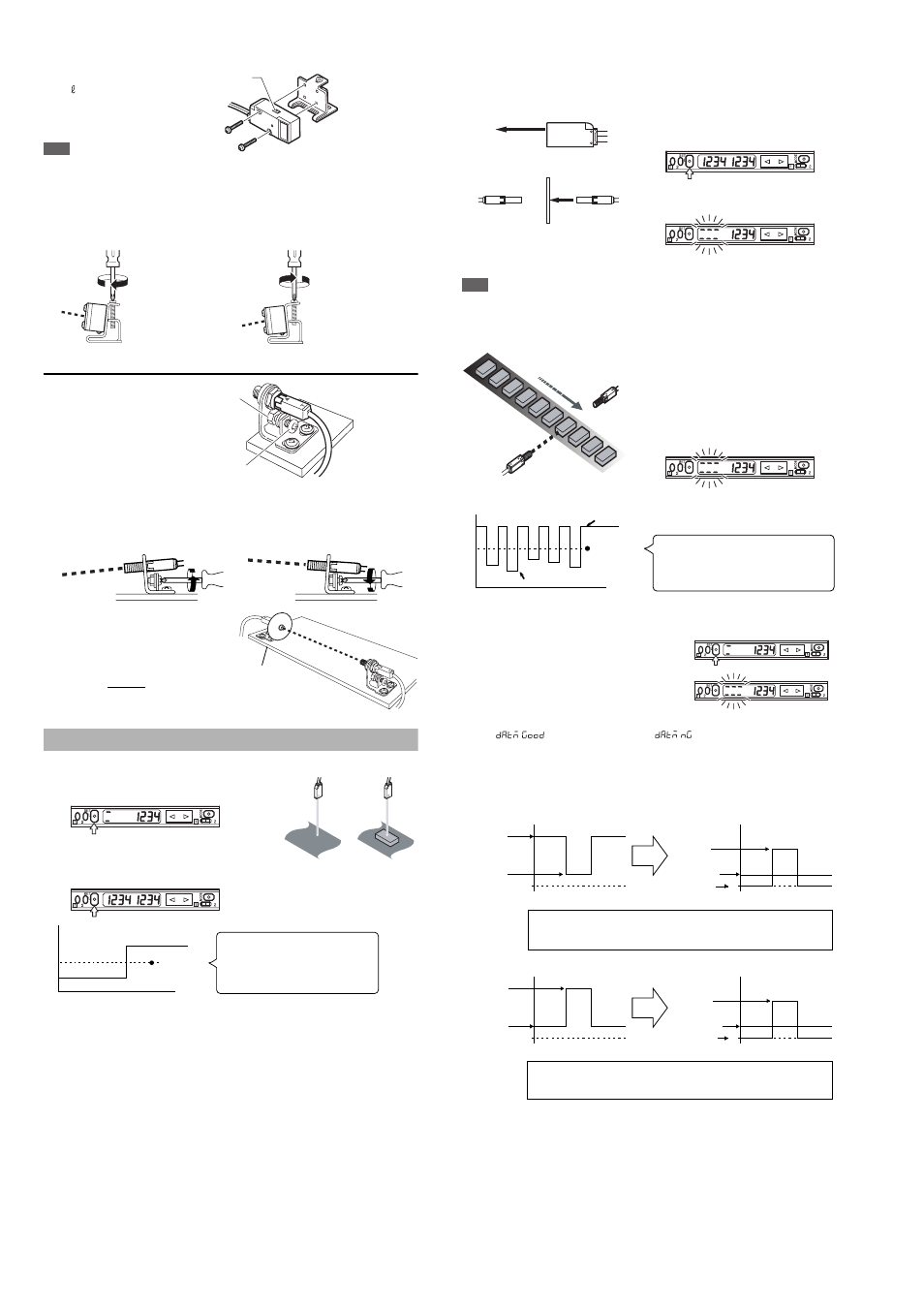
■ Side mounting bracket (sold separately: OP-84351)
Mounting bracket
1
M3 x 18 screw
2
Note
When mounting the sensor head in the opposite direction as described previ-
ously, set the spot toggle switch before mounting.
• Adjusting the beam axis
The angle of the beam axis can be changed upward if the screw indicated by
the arrow is tightened, and downward if loosened.
LV-S71/S72
Mount the sensor head such
that the letter “T” (on the
transmitter) or “R” (on the
receiver) faces upward. The
side where the operation indi-
cator illuminates should face
upward.
• Adjusting the beam axis
The angle of the beam axis can be changed downward if the screw indicated
by the arrow is tightened, and upward if loosened.
Adjust the spot to be emitted at the
center on the receiver.
The adjustment is facilitated by
attaching the beam-axis adjustment
cap supplied with the sensor head to
the tip of the receiver. Once the
adjustment is complete, remove the
beam-axis adjustment cap.
Setting Sensitivity
■ 2-point calibration
1
Press the SET button once without a
workpiece being placed.
2
Place a workpiece at the designated
position, and quickly press the SET
button once again.
* If the sensitivity difference does not have enough room, “++++” flashes after
the calibration is complete. The setting value is changed at this time, too.
■ Maximum sensitivity setting
Set the sensitivity without a workpiece in the case of the reflective type, and with
a workpiece in the case of the transmission type.
1
Press the SET button for three
seconds in the state as shown in
the figure on the left.
The indication flashes when the setting
is complete.
2
Release the SET button.
Note
In the transmission type, if the value for the maximum sensitivity setting is the same as
DSC, the device will not operate correctly, so do not use the same value.
■ Full-auto calibration (not available for the LV-S31)
1
Let the workpiece pass while the SET
button is being pressed for three
seconds. (The sensitivity is set
according to the received light intensity
while the SET button is pressed.)
2
The indication flashes when the
setting is complete.
3
Release the SET button.
Perform 2-point calibration if the setting cannot be configured as desired.
■ Zero datum calibration (not available for the LV-S31)
1
Press the SET button quickly without a
workpiece being placed.
2
Press the SET button for at least three
seconds. When the indication flashes,
release the button.
3
The calibration is complete when
"
" is displayed. When "
" is displayed, switch the
channel toggle switch to "2" and check the contents of the alarm.
*The alarm contents are only displayed when "Auto" is selected for "ALrt",
the operation of control output 2 in "4. Detection mode selection". (For
information about the display, see "Toggling the display" on page 9.)
Transmission/retro-reflective types
Reflective type
Spot toggle
switch
Limit the tightening
torque up to 0.5Nm
When you want to raise the beam axis.
When you want to lower the beam axis.
Fixing nut
Beam axis
adjusting screw
Limit the tightening
torque up to 1.2 Nm.
When you want to lower the beam axis
When you want to raise the beam axis
Beam axis
adjustment cap
1
2
Received light intensity
Setting value
Time
The value set at the intermediate point
between the received light intensity
measured when the SET button is pressed
for the first time and that measured when it
is pressed for the second time.
1
2
Reflective type
Transmission type
With no workpiece
With workpiece
Received light intensity
Setting value
Time
MAX
MIN
The value is set at the intermediate point
between the MAX value and the MIN value
of the received light intensity measured
while the SET button is pressed.
Received light
intensity without
workpiece
0
0
Received light
intensity with
workpiece
(Blocked light)
Received light
intensity without
workpiece
Blocked light
Setting value
In the transmission or retro-reflective type, when zero datum calibration is performed
without a workpiece, the received light intensity without a workpiece is used as zero and
the value indicates the amount of blocked light. The setting value is set automatically.
0
0
Received light
intensity without
workpiece
Received light
intensity with
workpiece
(Entered light)
Received light
intensity without
workpiece
Entered light
Setting value
In the reflective type, when zero datum calibration is performed without a
workpiece, the received light intensity without a workpiece is used as zero and the
value indicates the amount of entered light. The setting value is set automatically.