Hangar 9 1/4-Scale J-3 Cub ARF User Manual
Page 31
31
.Step 5
Secure.the.throttle.servo.in.the.fuselage.using.the.
hardware.provided.with.the.servo..Thread.a.clevis.onto.the.
threaded.rod.and.attach.the.clevis.to.the.servo.arm.
Note:.When.using.a.gas.engine.it.is.
recomended.that.an.RF.choke.ring.(JRPA029).
be.used..The.servo.lead.must.make.3.
passes.around.or.through.the.ring.
.Step 6
Remove.the.stopper.from.the.fuel.tank.using.a.Phillips.
screwdriver..Remove.the.fuel.lines.from.the.stopper.and.
set.them.aside..Prepare.the.tubing.by.placing.a.drop.of.
solder.on.the.ends.of.the.brass.tubing.as.shown..This.
will.keep.the.fuel.line.from.slipping.off.the.tube.when.
combined.with.the.following.steps.
.Step 7
Slide.gas.compatible.fuel.lines.back.onto.the.brass..
tubes..Use.fine.wire.to.secure.the.fuel.lines..The.wire..
is.placed.behind.the.solder.applied.in.the.previous.step..
to.keep.the.tubes.in.place.
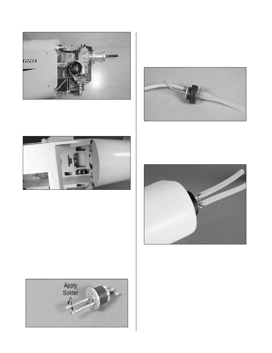
.Step 8
Carefully.insert.the.stopper.assembly.into.the.fuel.tank..
Note.the.position.of.the.vent.tube;.it.must.be.up.at.the.top.
portion.of.the.fuel.tank.to.function.properly..Tighten.the.
screw.carefully—do.not.over-tighten.
Engine Installation (Gas)