Landing gear installation, Landing.gear.installation – Hangar 9 1/4-Scale J-3 Cub ARF User Manual
Page 10
10
.
.Step 8
Repeat.Steps.1.through.8,.and.using.five.hinges.per.
aileron,.hinge.the.ailerons.to.the.wing.panels.
Required Parts
•.Fuselage.
•.Wheel.assembly.(2)
•.Wheel.axle.(2).
•.Cross.brace
•.Wing.strut.tab.(2).
•.4-40.locknut.(6)
•.4-40.setscrew.(2)
•.Assembled.shock.strut.(2)
•.Wheel.collar.w/setscrew.(2)
•.Main.gear.strut.(right.and.left)
•.4-40.x.1/2-inch.socket.head.screw.(2)
•.4-40.x.5/8-inch.socket.head.screw.(4)
•.8-32.x.3/4-inch.socket.head.screw.(8)
•.#2.x.5/8-inch.sheet.metal.screw.(8)
Required Tools and Adhesives
•.Threadlock
•.Hex.wrench.(included.in.kit.for.wheel.collars)
•.Phillips.screwdriver.(#1)
•.Hex.wrench:.3/32-inch,.1/8-inch
•.Nut.driver:.1/4-inch
Note:.Be.sure.the.6-32.bolts.that.
secure.the.landing.gear.legs.to.the.
landing.brackets.are.snug.to.minimize.
vibration,.but.allow.for.movement
.Step 1
Locate.the.left.and.right.main.gear.struts.and.the.wing.
strut.tab..Attach.the.front.of.the.landing.gear.using.two..
8-32.x.3/4-inch.socket.head.screws..The.rear.is.also.
secured.to.the.fuselage.using.four.8-32.x.3/4-inch.socket.
head.screws,.but.the.wing.strut.tabs.are.positioned.
between.the.landing.gear.and.fuselage.
Note:.Use.threadlock.on.the..
8-32.x.3/4-inch.socket.head.screws..
to.prevent.them.from.vibrating.loose.in.flight.
Landing Gear Installation
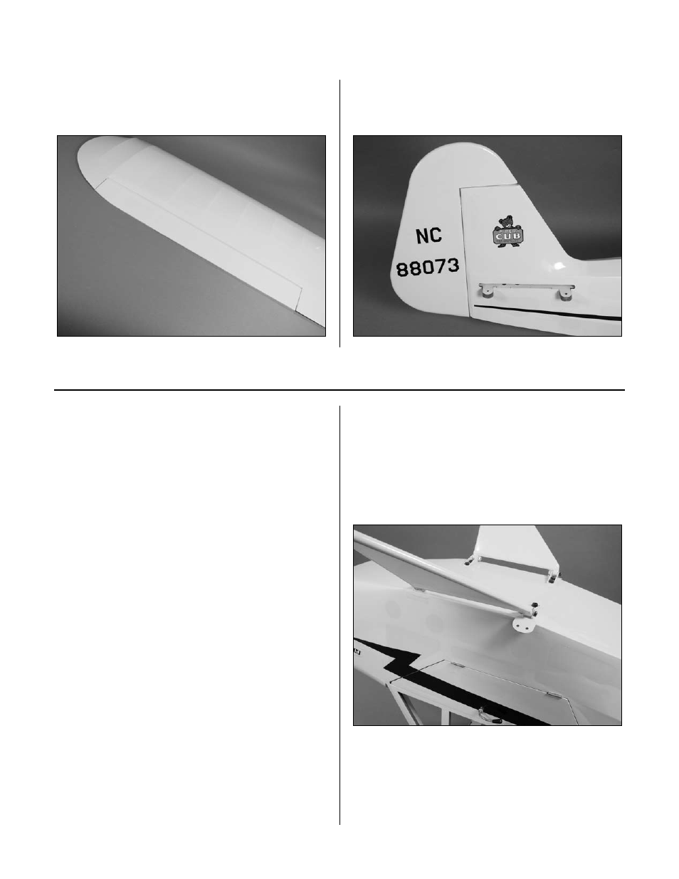
.Step 9
Repeat.Steps.1.through.8,.and.using.three.hinges,.hinge.
the.rudder.to.the.fin/fuselage.
Hinging the Control Surfaces