Appendix k - warranty repair and service – Brookfield DV-II+ Programmable Viscometer User Manual
Page 70
Brookfield Engineering Labs., Inc.
Page 70
Manual No. M/97-164-F1102
If the above do not rectify the problem, do the following:
✓ Shut off viscometer
✓ Attach printer.
✓ Press and hold the
MOTOR ON/OFF
and
ENTER/AUTORANGE
keys simulanteously while
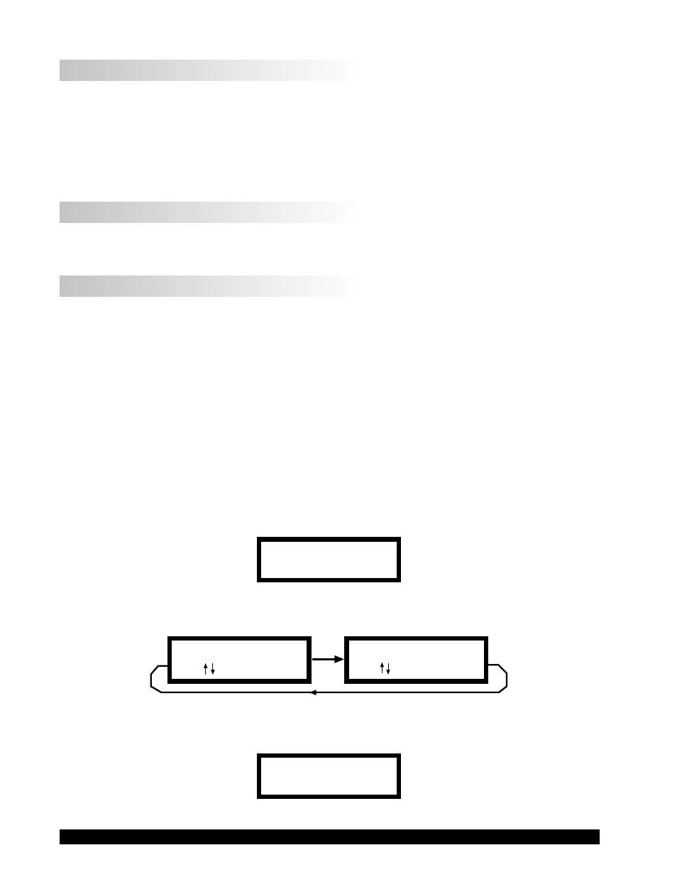
turning the viscometer power on. Figure J1 appears on the viscometer display.
VISCOMETER SETUP
ENTER TO START
Figure J1
✓ Press
ENTER/AUTORANGE
key and Figure J2 appears.
PRINT PARAM RAM?
NO THEN ENTER
PRINT PARAM RAM?
YES THEN ENTER
Figure J2
✓ Scroll to YES and press the
ENTER/AUTORANGE
key. Figure J3 appears.
READY PRINTER
ENTER TO START
Figure J3
❏
No Recorder Response
✓ Be Sure the viscometer is not at ZERO reading.
✓ Be sure the recorder is ON and not on STANDBY.
✓ Verify the range settings.
✓ Check cable leads for clean connection.
❏
Recorder Pen Moves in Wrong Direction
✓ Output polarity reversed
• Reverse leads
❏
Viscometer Will Not Communicate with PC
✓ Check the comm port and make sure the correct port is being utilized.
✓ Check the interconnecting cable for proper installation
✓ Check the Options menu and make sure the PC PROG is set to either “ON” or “OFF” in
accordance with the operating instructions for the program/procedure in use.