Gpio configuration dip switches, Gpio terminal blocks, Rs-232/422 port – Aviom 6416dio User Manual
Page 81: Rs‑232/422 port, Digital i/o module
71
v
irtuAl
d
AtA
c
Ables
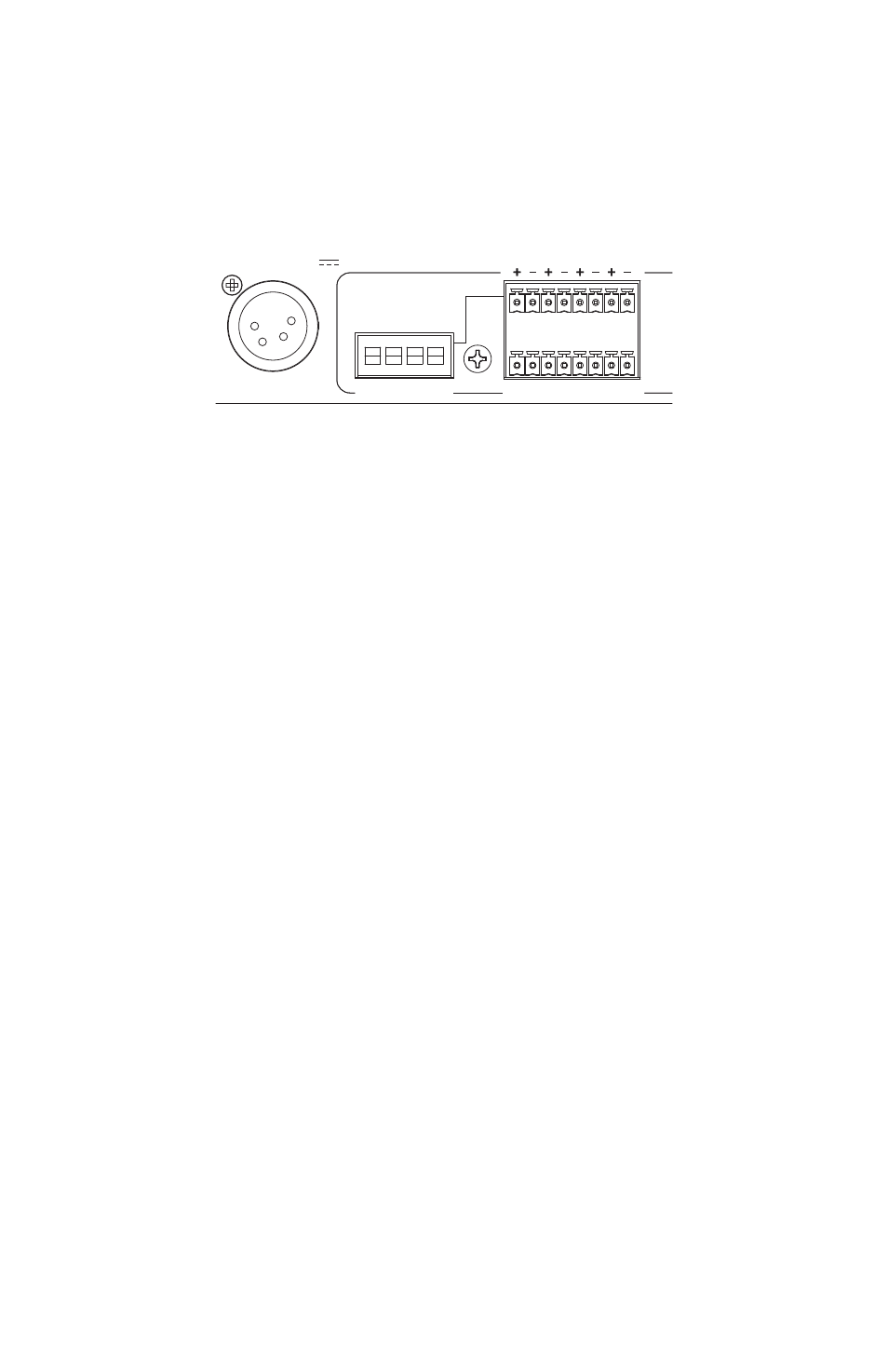
GPIO Configuration DIP Switches
Each of the four GPIO Input blocks can be set to either Isolated or TTL
operation using the configuration switches to the left of the terminal blocks.
75Ω
TERMINATION
B
A
Digital I/O Module
AES3 I/O CHANNELS 9–16
AES3 I/O CHANNELS 1–8
6416
dio
AC POWER
1 AMP
PIN 1 = GND
PIN 4 = 24VDC
IN
OUT
RS-232/422
FUSE: 250VAC-F4AL
BACKUP POWER
1 2 3 4
1
2
3
4
GPIO INPUT
UP = ISOLATED
DN = TTL
PORT SETUP
1–8
CTRL MASTER
232 / 422
10
12
RESERVED
9, 11
ON
WORD CLOCK
IN
75Ω
TERMINATION
OUT
DIGIDESIGN / TASCAM COMPATIBLE
YAMAHA COMPATIBLE
VIRTUAL DATA CABLE PORTS
The Isolated/TTL configuration switches only apply to the GPIO inputs.
With the switch in the down position, the input is set to TTL. Use this setting
for voltage‑type signals. GPIO inputs set for TTL operation can handle signal
voltages up to 5 Volts.
The up position (Isolated) sets the input to accept on/off switch signals.
Do not use the Isolated setting with voltage-based signals. See the
GPIO Specifications later in this document for additional configuration
information.
GPIO Terminal Blocks
Each GPIO input or output has a positive and negative contact that can
be wired as needed. Four of each are provided. Only a small screwdriver is
required.
RS-232/422 Port
The Pro64 RS‑232/422 VDC port allows a pair of devices to transfer either RS‑
232 or RS‑422 control data (user selectable) at rates up to 57.6k baud across
the Pro64 network. Using Virtual Data Cables for RS‑232/422 always requires
two VDCs because RS‑232/422 data transfers require communicating devices
to be set up in a handshaking pair. Note that RS‑232/422 communication is
point‑to‑point, meaning that a maximum of seven RS‑232 and/or RS‑422
connections (14 total devices) are possible when using Pro64 Virtual Data
Cables.