Bnc version i/o, Digital i/o module – Aviom 6416dio User Manual
Page 78
68
r
eAr
P
ANel
F
eAtures
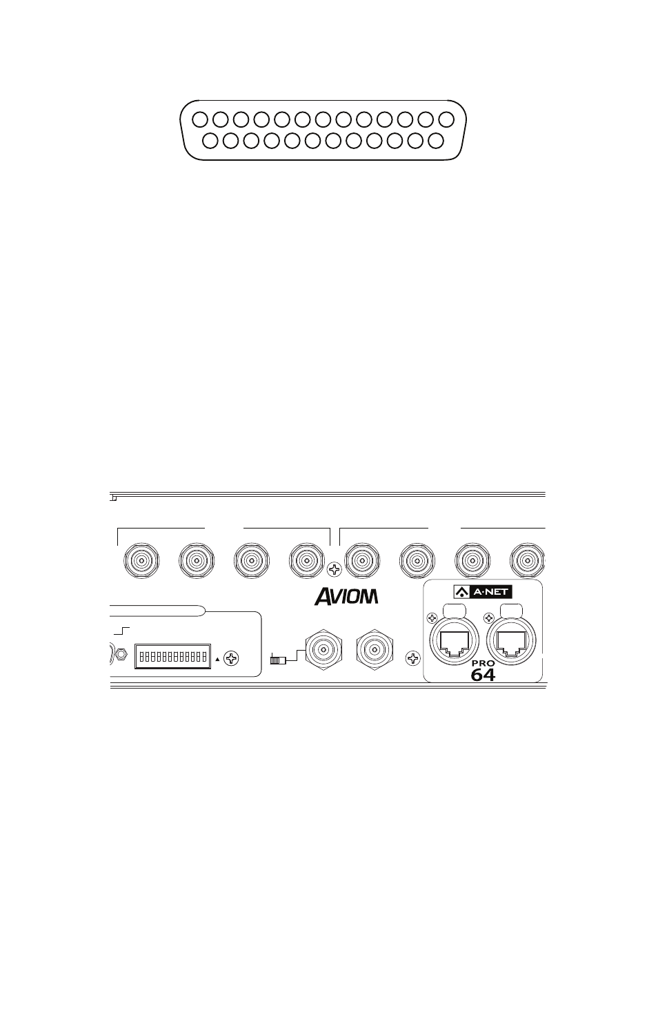
13 12 11 10 9 8 7 6 5 4 3 2 1
25 24 23 22 21 20 19 18 17 16 15 14
The pins on the panel-mounted DB25 jacks are numbered according to the
diagram above.
The DB25 panel‑mount connectors on the 6416dio Digital I/O Module rear
panel have #4‑40 UNC thread.
P
N
ote
: Strain relief is suggested when using DB25 cable assemblies. DB25
breakout cables should always be supported when connected to a
Pro64 product to reduce the risk of damaging the Pro64 product’s
rear panel.
BNC Version I/O
Sixteen digital input and output channels are available via 16 locking BNC
connectors. Each cable carries a pair of channels. Use 75 ohm cable for best
performance.
B
A
Digital I/O Module
AES3 I/O CHANNELS 9–16
AES3 I/O CHANNELS 1–8
INPUTS
OUTPUTS
INPUTS
OUTPUTS
6416
dio
AC POWER
FUSE: 250VAC-F4AL
1 AMP
BACKUP POWER
PIN 1 = GND
PIN 4 = 24VDC
IN
OUT
1 2 3 4
1
2
3
4
GPIO INPUT
UP = ISOLATED
DN = TTL
PORT SETUP
1–8
CTRL MASTER
232 / 422
10
12
RESERVED
9, 11
ON
RS-232/422
WORD CLOCK
IN
OUT
1/2
3/4
5/6
7/8
1/2
3/4
5/6
7/8
9/10
11/12
13/14
15/16
9/10
11/12
13/14
15/16
VIRTUAL DATA CABLE PORTS
75Ω
TERMINATION
Separate BNC jacks are provided for input and output signal pairs, 16 in all.
Do not connect video sources to the BNC digital I/O on the 6416dio rear
panel.