A-net slot display, A‑net slot display – Aviom 6416dio User Manual
Page 25
15
P
ro
64 u
ser
i
NterFAce
rate can be selected, but attempting to activate a channel in an unavailable
range will result in an error message (the selected channel button, A‑Net Slot
range, and sample rate LEDs will all flash).
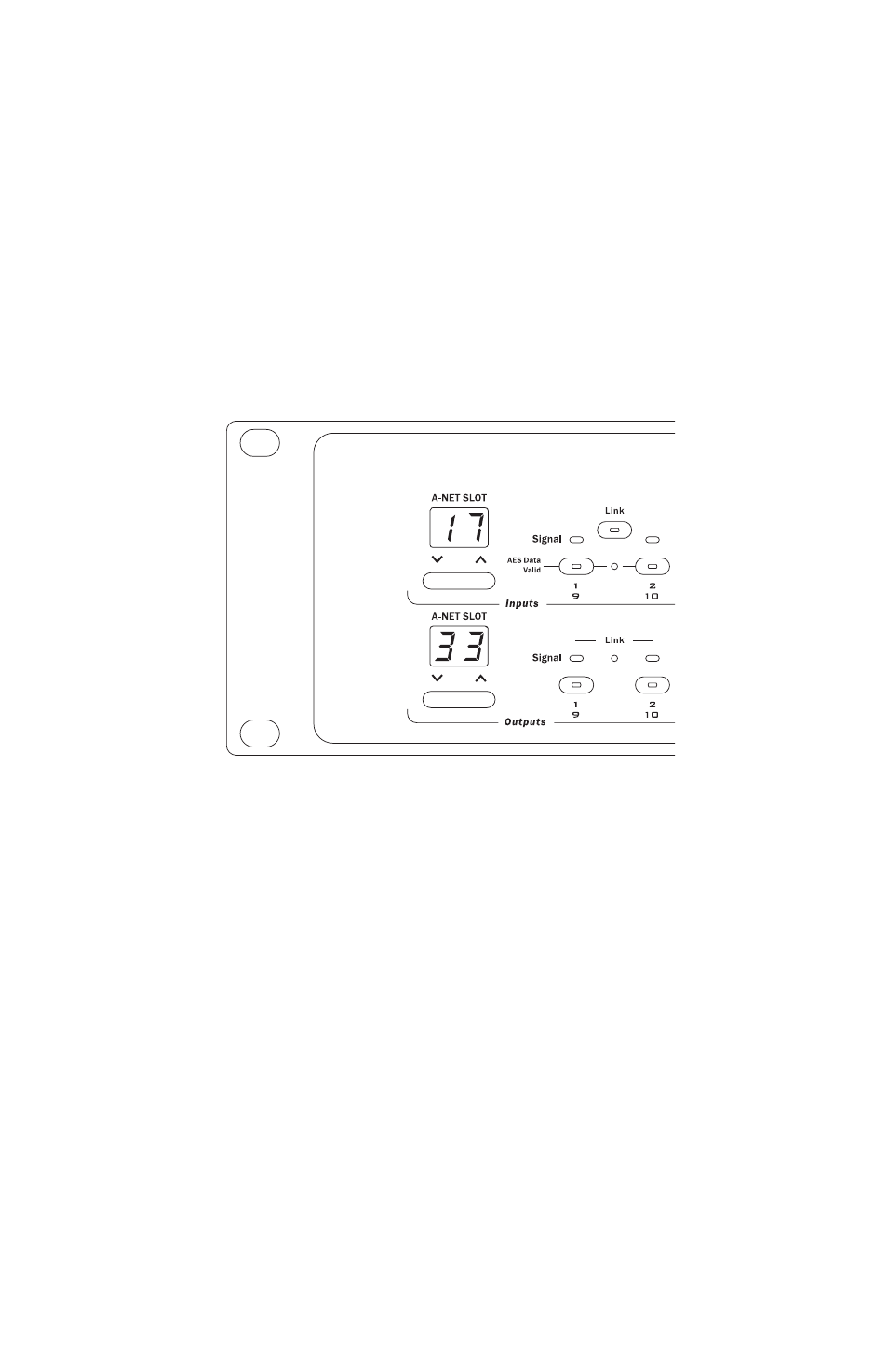
A-Net Slot Display
Since the capacity of the Pro64 network could be as high as 64 A‑Net Slots,
Pro64 hardware I/O devices need a way of routing a selected hardware
channel to a selected network Slot. In the upper left corner of the front panel
of a Pro64 I/O device, the A‑Net Slot display and its associated inc/dec buttons
are used to select a range of Slots that the hardware device will address.
The A-Net Slot display and its inc/dec buttons are used to set the base Slot
for a Pro64 I/O module. The 6416dio has separate displays for its inputs and
outputs.
The A‑Net Slot display will show the base number that is associated with the
first hardware input or output channel on an I/O device. The actual number
seen in this display will be determined by the physical I/O on the device. That
is, an 8‑channel device will display a different set of available starting points
than a 16‑channel device (see the following tables).
To select an A‑Net Slot range, use the inc/dec buttons below the display. Press
one of the buttons until the desired base Slot range is displayed, and then
press the
E
ntEr
button. To return to the current selection without making a
change, press the
C
anCEl
button.
The following tables show examples of the channel‑to‑Slot correlation
for Pro64 Series modules in a network running at the 48kHz sample rate.
The numbers in the Slot column will appear in the A‑Net Slot display. The
numbers seen to the right of each gray base Slot number correspond to the
channel buttons on the front panel of the interface.