Panasonic NN46240-502 User Manual
Page 72
Attention! The text in this document has been recognized automatically. To view the original document, you can use the "Original mode".
Nortel Secure Router 8000 Series
Configuration - LAN Access and MAN Access
4 VLAN configuration
4.4.2 Example of configuring VLANs to communicate with
non-VLANs through routers
Networking requirements
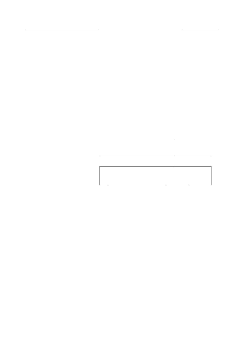
As shown in Figure 4-7, Switch A supports VLAN; while Switch B is not configured with any
VLAN.
The host members in VLAN10 must communicate with the hosts attached to Switch B.
Figure 4-7 Networking diagram of con^guring VLANs to communicate with non-VLANs
through a router
VLAN10
10.110.2.1/24
GE1/0/0.1
10.110.2.5/24
GE2/0/0
10.110.3.5/24
SwitchA
SwitchB
« «
VLAN20
^
1 1
10.110.4.1/24
10.110.3.1/24
Configuration roadmap
The configuration roadmap is as follows:
• Configure the encapsulation mode of the routed interface GE 1/0/0.1 connected with
Switch A to 802.1 Q.
• Configure GE 1/0/0.1 and VLAN 10 to be on the same network segment.
• Configure Switch B and the routed interface GE 2/0/0 connected with Switch B to be on
the same network segment.
Data preparation
To complete the configuration, you need the following data:
• The interfaces that connect Switch A and the hosts are divided into VLAN10 and
VLAN20.
• The IP address of GE 1/0/0.1 is 10.110.2.5.
• The IP address of GE 2/0/0.1 is 10.110.3.5.
Issue 5.3 (30 March 2009)
Nortel Networks Inc.
4-13