Interfacing, Parallel interfacing, Specifications – Panasonic KX-P 1131 User Manual
Page 40: Timing chart, Serial interfacing
Attention! The text in this document has been recognized automatically. To view the original document, you can use the "Original mode".
Interfacing
This information should be provided to the company from which you are purchasing the interface cable to ensure
the proper wiring of the cable.
Parallel Interfacing
A method of transferring data from a computer to a printer through a parallel interface is based on the Centronics
Standard.
Specifications:
___
• Data transfer speed: 1000 cps minimum
• Synchronization: External STROBE pulse
• Logic levels: TTL (Transistor-Transistor-Logic)
levels
18 1
o o o o o o o o o o o o o o o o o o
o o o o o o o o o o o o o o o o o o
\36
Parallel Interface Connector (printer side)
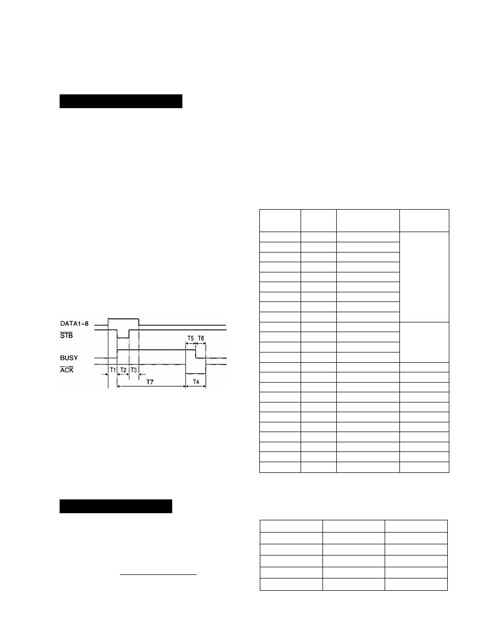
Timing Chart
(When normal printing code is received)
T1 . .
T2 . .
T3 . .
T4 . .
T5, T6
T7 . .
0,5 ps (Min)
0.5 ps (Min)
0.5 ps (Min)
Approx. 8 ps
Approx. 4 ps
1 ms or less when buffer is not full
1 s or less when buffer is full
Timing Diagram
•Handshaking: BUSY and ACK signals
• Connector type: 57-30360 (AMPHENOL) or
equivalent
• Cable: Use a shielded cable 1.95 m (6'5") or less in
length.
Signal
pin
Return
side pin
Signal
Direction
1
19
wxB
Input
2
20
DATAI
3
21
DATA 2
4
22
DATA3
5
23
DATA 4
6
24
DATAS
7
25
DTAT6
8
26
DATA 7
g
27
DATAS
10
28
ÂCK
Output
11
29
BUSY
12
PO
13
SLOT
14
AUTO FEED XT
Input
15
16
SG
17
FG
18
+5 V
Output
31
30
PRIME
Input
32
ERROR
Output
33
34
35
36
SLOT IN
Input
Pin Configuration
Serial Interfacing
Cable: Use a shielded cable 1.95 m (6'5") or less in
length.
\ . © © © © © © © © © © © © © i
\ t ^ ® © ® ® © © ® © © © © ® ^ / / ^
40
Serial Interface Connector (printer side)
Signal pin
Signal
Direction
1
FG
2
TXD
OUTPUT
3
RXD
INPUT
7
SG
20
DTR
OUTPUT
Pin Configuration