Chapter 1 overview – CANOGA PERKINS N525 Ethernet Termination Service Unit User Manual
Page 9
N525 Ethernet Termination Service Unit
1-1
Chapter 1
Overview
The N525 Series 10/100/1000BASE Ethernet Termination Service Unit terminates Metro
Ethernet Services and extends Local Area Networks (LANs) located up to 100 Km apart.
Key features are:
• Layer 2 statistics
• VLAN assignment and stacking
• Priority bit (P-Bit) marking
• Alarm information reporting
• Local and remote diagnostic loopback
• Remote software upgrade
• Remote control and monitoring through the SideBand Management Channel (SBMC)
The N525 receives and transmits 10/100/1000BASE Ethernet data on UTP copper cable,
single mode fiber optic cable, or multimode fiber optic cable. The N525 supports two hot-
swappable, plug-in interface modules. The interface modules include tri-speed (10/100/1000
Mbps) UTP and a variety of 850nm, 1310nm, 1550nm, CWDM Wavelength, and Single
Fiber BiDi optical interfaces at 10 Mbps, 100 Mbps and Gigabit. Optical interfaces are listed
in Chapter 5.
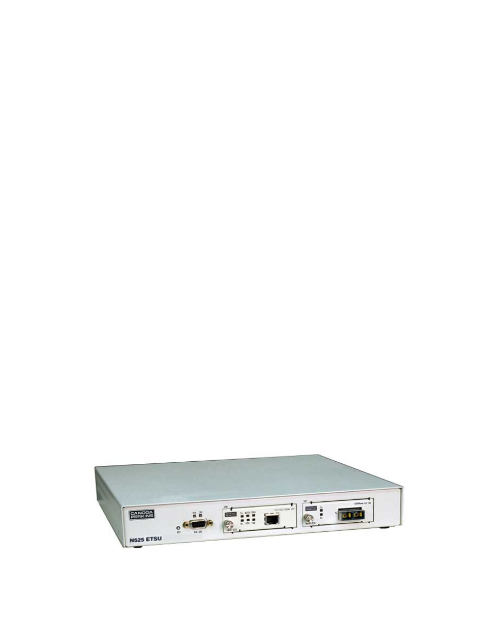
The N525 front panel, shown in Figure 1, includes:
1. User and Extension ports; supports UTP, ST, SC and LC connectors (depending on
Interface Module Type).
2. RS-232 Serial Management Port; support VT100 Terminal emulation and SLIP/PPP
3. Status LEDs:
• STA shows N525 status
• CFG shows configuration and setup status
• 100, 1000, and half/full duplex, depending on the type of module, show status
for the User port
• LNK/RX and TX pairs for the User and Extension ports show that data is
received and transmitted
Figure 1 – N525