Vernier LabPro User Manual
Page 69
Revision Date: 08/02/02
LabPro Technical Manual
69
Syntax: {401, waveform, amplitude, offset, period}
Parameter List: (note: all parameters are mandatory)
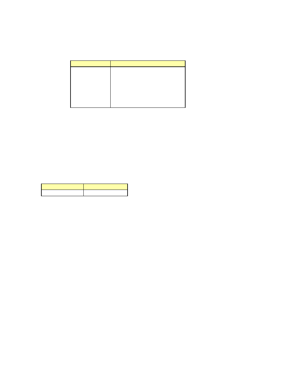
waveform
– indicates which waveforms will be generated. The possible values are
waveform
Description
0
OFF
1
DC Output
2
Ramp Up
(Sawtooth)
3
Ramp Down
(Sawtooth)
4
Triangle
5
Square
6
Sine
amplitude
– indicates which height of the wave. The possible values are from 0 to 4095.
See Sine examples for exceptions.
offset
– indicates where the wave will be centered. The possible values are from 0 to 4095.
period
– indicates how often (in milliseconds) the waveform will repeat itself. The number must be
an integer between 5 and 2000. As a result, the range of possible frequencies is 0.5 Hz to
200 Hz.
Return values: No information is returned. However, the output voltage will be produced as
follows:
V
out
= 0.0024*amplitude – 0.0012*offset where the result must satisfy –3V < Vout < 3V
Example 1:.
Computer
Calculator
s{}
:Send({})
Examples:
DC Voltage: The easiest way to produce a DC output is usually to control the amplitude and set the offset
to 0 for positive values and control the offset and set amplitude to 0 for negative output values.
401,1,1023,0,0
Vout
= 2.5V signal.
401,1,0,2048,0
Vout
= –2.5V signal
401,1,1023,1023,0
Vout
= 1.25 V signal
Ramp:
401,2,2048,2048,10
Vout
= 100Hz ramp up pk-pk = 5V centered about 0
( pk voltage = 2*2048*1.2mV – 2048*1.2mV)
401,3,1023,0,20
Vout
= 50Hz ramp down pk-pk = 2.5V centered about 1.25V
Sine
401,6,0,3072,10
Vout
= 100Hz Sine wave pk-pk = 8V centered about 0
(pk voltage = 2*3072*1.2mV – 3072*1.2mV)
401,6,1,1536,10
Vout
= 100Hz Sine wave pk-pk = 4V centered about 0
401,6,2,768,10
Vout
= 100Hz Sine wave pk-pk = 1V centered about 0
NOTE: Sine wave may be improved by adding a low pass filter to output.
Turn off Analog Out:
401,0,0,0,0
NOTE: MUST PASS ALL PARAMETERS