Digital output buffer example, Analog outputs – Vernier LabPro User Manual
Page 19
Revision Date: 08/02/02
LabPro Technical Manual
19
Digital Output Buffer Example
Command 1 list is {1,31,5,1,2,3,4,5} where:
Command 3 list is {3,1,100}
where:
1=Channel Setup.
31=DIG OUT.
5=Five data elements.
1=0001 (digital nibble).
2=0010 (digital nibble).
3=0011 (digital nibble).
4=0100 (digital nibble).
5=0101 (digital nibble).
3=Sample and Trigger Setup.
1=One second sample time.
100=One hundred samples.
(Trigger Type defaults to manual
triggering.)
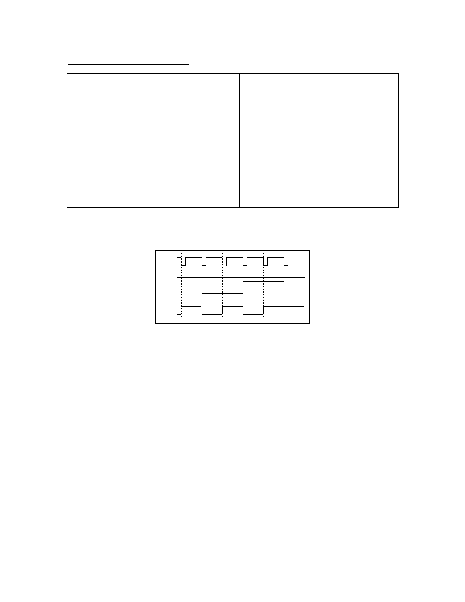
The DOB outputs pulses that correspond to the five digital nibbles (1234512345...12345 etc.). This
sequence is repeated 20 times (100 samples/5 data elements) to the DIG OUT channel. The diagram below
shows a portion of this output for the first five data elements.
Sample
Clock
1
2
3
4
5
1
D3
D2
D1
D0
Figure 1. Digital Output Example
Analog Outputs
The analog output is present on line 1 of CH4. Once the channel has been setup, the output is enabled
immediately regardless of data collection mode. It will remain active until the unit is reset or until it is
disabled using Command 401
When the output is activated using Command 401, the driving voltage may be monitored by reading Vin
on CH4.
The voltage out is limited to +/- 3 V and to +/- 100 mA. By changing the parameters you may change the
output value. A variety of waveforms are supported. Command 401 allows the program to set a waveform,
amplitude, offset and period and the analog output will generate the desired waveform. The official syntax
for this command is:
401, waveform, amplitude, offset, period
The current Lab Pro operating system revision understands the following parameter:
waveform = DC voltage, ramp up, ramp down, triangle, sine
amplitude = the peak to peak voltage
offset = the voltage relative to ground