Command 12 digital data capture – Vernier LabPro User Manual
Page 51
Revision Date: 08/02/02
LabPro Technical Manual
51
Command 12
Digital Data Capture
This command sets up the capture of data from the digital input channels. The digital lines are electrically
“pulled” high so that the LabPro digital lines have a default state. Each DIG/SONIC port consists of four
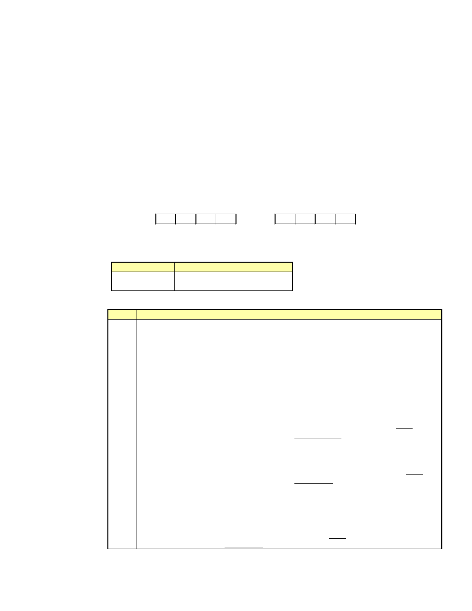
digital lines. Command 12 reads a single line of each DIG/SONIC port. Figure 1 illustrates how the digital
lines are physical mapping. When Command 12 is used, the power generally stays on during sampling. As
a result, this mode tends to deplete the batteries very quickly. The number of data samples taken is limited
only by the available memory after memory is reserved for the Command 1 channels that are set up. LabPro has
about 12,000 available memory locations. If X channels are setup and Y samples are selected using Command
3, the number of samples on CH 41 is limited to (12,000 – X*Y)/3.You absolutely must have at least one
analog channel activated before sending the Command 3 to start sampling.
Syntax:{12, channel, mode[, P1[, P2]]}
Port
Bit Value
128
64
32
16
8
4
2
1
DIG/Sonic1
DIG/Sonic2
Parameter List:
channel
– indicates which channel to work with. The possible values are
Channel number
Description
41
DIG/SONIC Channel 1
42
DIG/SONIC Channel 2
mode
– indicates what type of digital data collection to perform. The possible values are
mode
Use
-2
Returns a list of numbers based on collection mode (>0), {see individual collection modes for
definition of list} P1 and P2 are the data row indices, or Start and Stop
position for a block of data (see below).
-1
Returns a list of numbers based on collection mode (>0), {see individual collection modes for
definition of list} P1 and P2 are the data row indices, or Start and Stop
position for a block of data (see below).
0
return number of points collected on next get statement; send after “getting” the analog
channels
1
Sample Mode
This mode is used when none of the other modes (below) are useful. In
this mode, each time the data changes, it is recorded in LabPro. This
allows for any new digital probes to be used if the user is willing to write
the program to process the data. Mode –2 will return a list of times and
Mode –1 will return a list of final line states.
2, 3
Measures pulse width of the data on the DIG/SONIC channel. This mode is used with a
photogate to get very accurate measurement of the time a photogate is
blocked. Generally, this measurement is used to determine the speed of an
object (must know object’s length). Mode –2 will return a list of times and
Mode –1 will return a list of pulse widths based on the Direction indicated
by parameter P1 (see below).
4
Measures period
of the data on the DIG/SONIC channel. This mode is used with a
photogate to get very accurate measurement of the times between when
the photogate becomes blocked. Generally, this measurement is used to
determine the speed of a wheel or a picket fence or the period of a
pendulum. Mode –2 will return a list of times and Mode –1 will return a
list of cycle widths.