Carrier 69NT40-511-199 User Manual
Page 51
SECT
IO
N
3
3-13
T-268-07
CODE
#
DESCRIPTION
TITLE
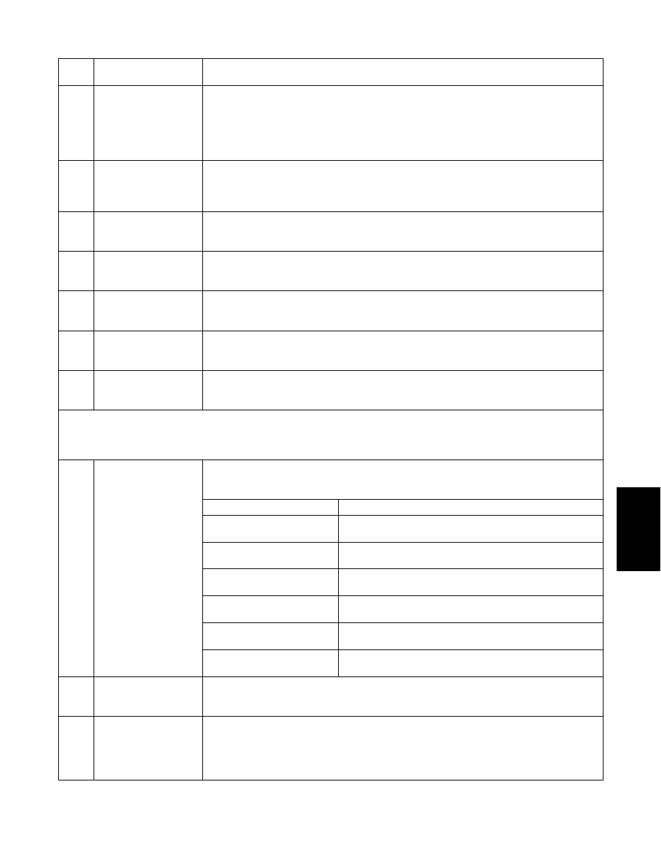
AL63 Current Over Limit
Alarm 63 is triggered by the current limiting system. If the compressor is ON and
current limiting procedures cannot maintain a current level below the user
selected limit, the current limit alarm is activated.This alarm is a display alarm and
is inactivated by power cycling the unit, changing the current limit via the code
select Cd32, or if the suction modulation valve (SMV) is allowed to open to 100%
and the suction solenoid valve is allowed to open.
AL64
Discharge
Temperature Over
Limit (CPDT)
Alarm 64 is triggered if the discharge temperature is sensed greater than 135_C
(275_F) for three continuous minutes, if it exceeds 149_C (300_F), or if the
sensor is out of range. This is a display alarm and has no associated failure
action.
AL65
Discharge Pressure
Transducer Failure
(DPT)
Alarm 65 is triggered by a compressor discharge transducer reading outside the
valid range of 73.20 cm Hg (30 in Hg) to 32.34 Kg/cm
2
(460 psig). This is a
display alarm and has no associated failure action.
AL66
Suction Pressure
Transducer Failure
(SPT)
Alarm 66 is triggered by a suction pressure transducer reading outside the valid
range of 73.20 cm Hg (30 in Hg) to 32.34 Kg/cm
2
(460 psig). This is a display
alarm and has no associated failure action.
AL67 Humidity Sensor
Failure
Alarm 67 is triggered by a humidity sensor reading outside the valid range of 0%
to 100% relative humidity. If alarm AL67 is active and the dehumidification mode
was previously activated, then the dehumidification mode will be deactivated.
AL68
Condenser Pressure
Transducer Failure
(CPT)
Alarm 68 is triggered by a condenser pressure transducer reading outside the
valid range of 73.20 cm Hg (30 in Hg) to 32.34 Kg/cm
2
(460 psig). This is a
display alarm and has no associated failure action.
AL69
Suction Temperature
Sensor Failure
(CPSS)
Alarm 69 is triggered by a suction temperature sensor reading outside the valid
range of --60_C (--76_F) to 150_C (302_F). This is a display alarm and has no
associated failure action.
NOTE
If the Controller is configured for four probes without a DataCORDER, the DataCORDER alarms AL70
and AL71 (See Table 3-7) will be processed as Controller alarms AL70 and AL71.
The Controller performs self-check routines. if an internal failure occurs, an ERR
#0--5 will appear on the display. This is an indication the Controller needs to be
replaced.
ERROR
DESCRIPTION
#0 -- RAM failure
Indicates that the Controller working memory has
failed.
ERR Internal
Microprocessor
#1 -- Program Memory
failure
Indicates a problem with the Controller program.
ERR
#
Microprocessor
Failure
#2 -- Watchdog time--out
The Controller program has entered a mode whereby
the Controller program has stopped executing.
#3 -- On board timer
failure
The on board timers are no longer operational. Timed
items such as; defrost, etc. may not work.
#4 -- Internal counter
failure
Internal multi-purpose counters have failed. These
counters are used for timers and other items.
#5 -- A-D failure
The Controller’s Analog to Digital (A-D) converter has
failed.
Entr
StPt
Enter Setpoint
(Press Arrow &
Enter)
The Controller is prompting the operator to enter a set point.
LO
Low Mains Voltage
(Function Codes
Cd27--38 disabled
and NO alarm
stored.)
This message will be alternately displayed with the set point whenever the mains
voltage is less than 75% of its proper voltage.