Carrier 69NT40-511-199 User Manual
Page 111
SECT
IO
N
6
6-17
T-268-07
by holding the spanner wrench stationary and
turning the 5/8-18 nut counter-clockwise (see
Figure 6-18).
1
2
3
4
5
6
5
7
8
9
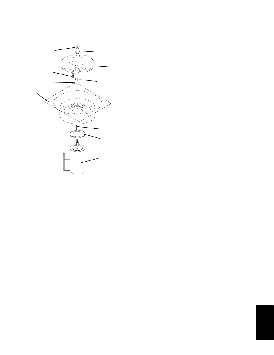
1. Stator
2. Flat washer, 1/4
3. Bolt, 1/4-20 x 3/4
4. Locknut, 5/8-18
5. Flat washer, 5/8
6. Impeller Fan
7. Key
8. Mylar Protector
9. Evaporator Motor
Figure 6-18. Evaporator Fan Assembly
2. Remove the spanner wrench. Use a universal wheel
puller and remove the fan from the shaft. Remove
the washers and key.
3. Remove the four 1/4-20 x 3/4 long bolts that are
located under the fan that support the motor and
stator housing. Remove the motor and plastic
spacer.
To assemble the Evaporator Fan Assembly:
1. Assemble the motor and plastic spacer onto the
stator.
2. Apply loctite to the 1/4-20 x 3/4 long bolts and
torque to 0.81 mkg (70 inch-pounds).
3. Place one 5/8 flat washer on the shoulder of the fan
motor shaft. Insert the key in the keyway and
lubricate the fan motor shaft and threads with a
graphite-oil solution (such as Never-seez).
4. Install the fan onto the motor shaft. Place one 5/8
flat washer with a 5/8-18 locknut onto the motor
shaft and torque to 40 foot-pounds.
d. Install the evaporator fan assembly in reverse order
of removal. Torque the four 1/4-20 clamp bolts to
0.81 mkg (70 inch-pounds) Apply power
momentarily to check for proper fan rotation (refer
to section 2.3). If fan spins backward, then motor
wiring or motor is defective.
e. Replace access panel making sure that panel does
not leak. Make sure that the T.I.R. locking device is
lockwired.
6.16 EVAPORATOR FAN MOTOR CAPACITORS
The evaporator fan motors are of the permanent-split
capacitor type. The motor is equipped with one
capacitor (used in the high speed circuit) and another
capacitor used for the low speed circuit.
a. When to check for a defective capacitor
1. Fan motor will not change speed. For example:
controller settings above --10_C (+14_F), or --5_C
(+23_F) optionally, should cause the motor to run in
high speed.
NOTE
The evaporator fan motors will always start in
high speed.
Controller settings below --10_C (+14_F), or --5_C
(+23_F) optionally, should cause the motor to run in
low speed.
2. Motor running in wrong direction (after checking
for correct wiring application).
b. Removing the capacitor
WARNING
Make sure power to the unit is OFF and
power plug disconnected before removing
capacitor(s).
1. The capacitor located on the motor and above the
evaporator fan deck may be removed by two methods:
(a) If container is empty, open upper rear panel of
the unit. The capacitor may be serviced after
disconnecting power plug.
(b) If container is full, turn the unit power OFF and
disconnect power plug. Remove the evaporator
fan motor access panel. (See Figure 2-1). For
removal of the evaporator fan assembly, refer to
section 6.15.