Installation guidelines – Waterworks 25 Thermostatic Valve User Manual
Page 2
PRODUCT SUPPORT 800.927.2120 8am - 6pm EST
.25
THERMOSTATIC VALVE
INSTALLATION GUIDELINES
Page 2 of 2
6.18.2014
These guidelines have been prepared for the professional contractor to aid in the installation of:
.25 THERMOSTATIC VALVE STYLE NO. GUTH78, GU78TH (UK)
All dimensions are based on original specification and are subject to change and variation.
Please consult your Design Associate for current specifications.
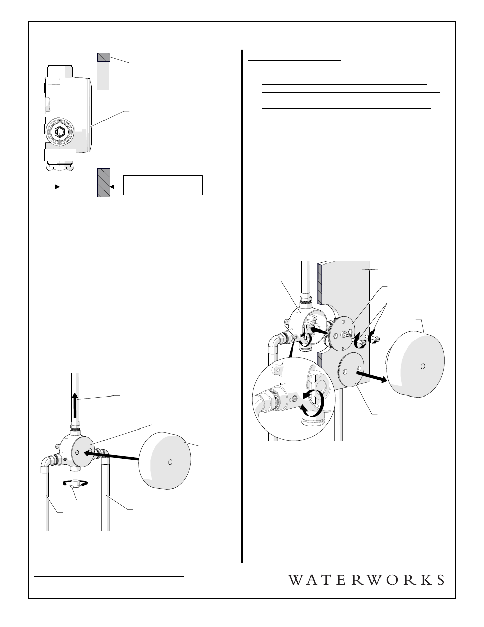
FLUSH OUT THE SYSTEM:
¾ Before installing the cartridge, the supply lines must
be flushed out to prevent clogging of the filter
screens. Failure to flush the lines will permanently
damage the cartridge and void the warranty. Repeat
this process as needed prior to trim installation.
¾ See Figure - 04 for steps 7-11.
7. The VALVE BODY is shipped with the FLUSH PLATE
pre-installed, and is ready for flushing the lines.
8. Turn on the water supply and open the SERVICE
STOPS to flush out the lines then inspect all
connections for leaks.
9. After the lines are flushed, turn off the water supply
and close the SERVICE STOPS, unthread the 2 cover
SCREWS, then remove the FLUSH PLATE.
10. Install the CARTRIDGE using the 2 cover SCREWS
and turn off the SERVICE STOPS.
11. Re-attach the TILE GUARD to protect CARTRIDGE .
TILE
GUARD
FINISHED
WALL
VALVE
BODY
SERVICE
STOP
CARTRIDGE
FLUSH PLATE
SCREWS
TILE
GUARD
FINISHED
WALL
VALVE
BODY
SERVICE
STOP
CARTRIDGE
FLUSH PLATE
SCREWS
FIGURE - 04
¾ If further assistance is required, please contact
Product Support at 1-800-927-2120 (8am-6pm EST).
¾ See service part document for parts ordering,
available on WATERWORKS.COM.
† BSP Adapter can be ordered separately:
(4x)
STYLE No. UNUK01
ITEM No. 45-22566-33137
FINISHED
WALL
.25 THERMOSTATIC VALVE
(FLUSH PLATE PRE-INSTALLED)
FINISHED
WALL
.25 THERMOSTATIC VALVE
(FLUSH PLATE PRE-INSTALLED)
ROUGH-IN DEPTH
3-1/8" MIN - 4" MAX
(79mm MIN - 102mm MAX)
CENTER OF
INLETS
FIGURE - 02
¾ See Figure - 03 for steps 3-6.
3. Run 3/4" (22mm) copper supply lines to the proper
height of the valve inlets and be sure to secure all
piping and fittings.
4. For each fitting that will have water flowing to it,
install a wall valve or diverter valve (both sold
separately) at the same rough in depth and
according to the flow direction arrow marked on the
wall valve or diverter valve body.
5. The bottom port of the valve body has a PLUG pre-
installed, but can be removed and the bottom port
can be used to supply water to other fittings.
6. Install the TILE GUARD to protect the valve during
the completion of the finished wall and to create the
exact opening for access to the service stops and
future servicing.
3/4" (22mm)
COLD SUPPLY
PLUG
.25 THERMOSTATIC VALVE
(FLUSH PLATE PRE-INSTALLED)
OUTLET
TO VOLUME
CONTROL VALVE
(SOLD SEPARATELY)
3/4" (22mm)
HOT SUPPLY
TILE
GUARD
3/4" (22mm)
COLD SUPPLY
PLUG
.25 THERMOSTATIC VALVE
(FLUSH PLATE PRE-INSTALLED)
OUTLET
TO VOLUME
CONTROL VALVE
(SOLD SEPARATELY)
3/4" (22mm)
HOT SUPPLY
TILE
GUARD
FIGURE - 03