Waterworks Highgate Exposed Deck Mounted Tub Filler With White Porcelain Handshower User Manual
Installation guidelines
HIGHGATE
Deck Mounted Tub Filler With Handshower
INSTALLATION GUIDELINES
Page 1 of 3
6.11.2012
These guidelines have been prepared for the professional contractor to aid in the installation of:
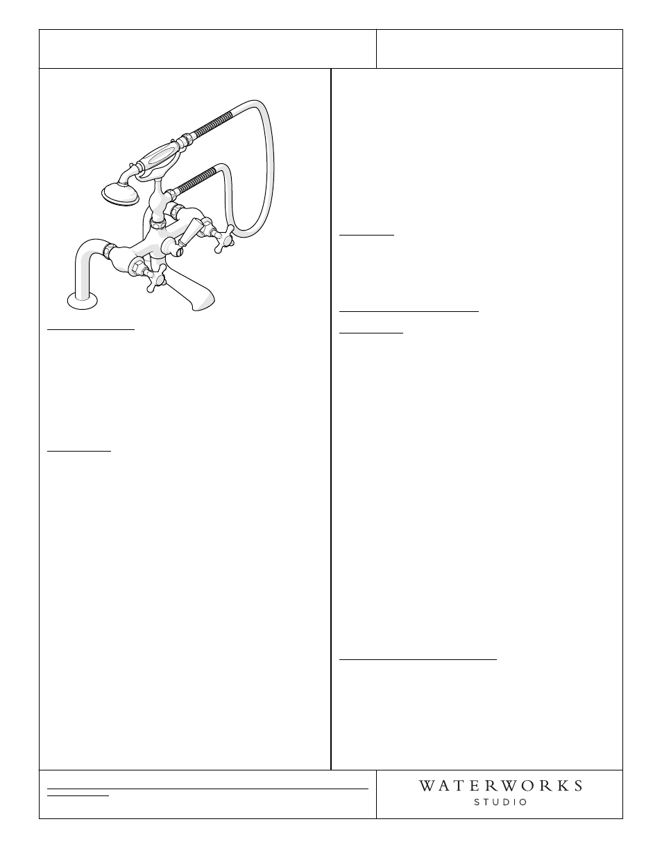
HIGHGATE DECK MOUNTED TUB FILLER WITH HANDSHOWER & METAL CROSS HANDLES
(STYLE# HGXT40)
All dimensions are based on original specification and are subject to change and variation.
Please consult your Design Associate for current specifications.
Metal Cross Handles
Style No. HGXT40
SPECIFICATIONS:
Handle Spread: 7-5/8" (NOT ADJUSTABLE)
Inlet Connection Size: 3/4"
Inlet Connection Type: Male NPT
Inlet Connection Spread 7-5/8" (NOT ADJUSTABLE)
Maximum Water Pressure: 80psi
Minimum Water Pressure: 20psi
Fittings Hole Diameter: 1-1/4"
Recommended Water Pressure: 45psi
Spout Reach: 9-13/16"
IMPORTANT:
¾
To ensure this product is installed properly, you
must read and follow these guidelines.
¾
The owner/user of this product must keep this
information for future reference.
¾
Be sure your installation conforms to federal state,
and local codes. Anti-scald protection is the
responsibility of the installer and according to
applicable codes.
¾
In the State of Massachusetts, all installations must
comply with the rules and regulations set forth
within 248 CMR.
¾
This product must be installed by a professional
licensed contractor.
¾
Product should be on-site prior to rough-in. This
allows the installer to visualize the installation and
verify the inlet connection spread.
¾
Refer to the specifications and assembly drawings
attached. Product is sold partially assembled but
shown fully disassembled for illustrative and service
purposes only.
¾
Check tub measurements to assure the spout
projects far enough into the tub.
¾
Inspect this product to ensure you have all the parts
required for proper installation.
¾
Use only a strap wrench or protected/smooth-jaw
wrench on any finished surface.
¾
Run 3/4" supply lines for maximum flow.
¾
Install accessible hot and cold service stop valves to
facilitate servicing.
ROUGH-IN:
1.
Run well supported 3/4" hot and cold supply lines
for maximum water flow. The inlet supply spread is
7-5/8" on-center and is not adjustable. 1-1/4" drilling
for the mounting holes is recommended.
TUB FILLER INSTALLATION:
IMPORTANT:
¾
Verify the 7-5/8" inlet supply spread prior to
installation.
2. Remove the 3/4" NPT adapter (8), the washer (7)
and mounting hardware (4, 5, & 6) from each deck
union (1).
3. Ensure that each escutcheon (2) is fully threaded up
the deck union (1).
4. Insert the unions into the deck, making sure that the
washers (3) are between the escutcheons and the
deck.
5. Re-install the mounting hardware (4, 5, & 6) onto
each union.
6. Tighten the nuts (6) up against the underside of the
deck to secure the unions.
7. Insert a washer (7) into each adapter (8) then thread
the adapters onto the unions (1).
8. Hold the valve body (9) up to the unions (1) and
attach it by threading the valve body union nuts
onto the unions. Ensure that a washer (7) is in each
nut.
HANDSHOWER INSTALLATION:
9. Attach the handshower cradle (12) to the valve body
(9) and ensure that washer (7) is located in the
cradle inlet. NOTE: A check valve is located at the
inlet of the cradle and a flow regulating check valve
is located at the outlet of the cradle.
10. Connect one end of the handshower hose (11) to the
handshower (10).