Installation guidelines – Waterworks Ludlow Three Way Diverter Trim for Thermostatic System with Lever Handle User Manual
Page 2
PRODUCT SUPPORT 800.927.2120 8am - 6pm EST
LUDLOW
Diverter Trim Plates
INSTALLATION GUIDELINES
Page 2 of 2
2.11.2014
These guidelines have been prepared for the professional contractor to aid in the installation of:
LUDLOW DIVERTER TRIM PLATES (STYLE# SEE ABOVE) All dimensions are based on original
specification and are subject to change and variation.
Please consult your Design Associate for current specifications.
SEE SERVICE PART DOCUMENT FOR PART ORDERING, AVAILABLE ON WATERWORKS.COM
IMPORTANT:
¾ To ensure this product is installed properly, you
must read and follow these guidelines.
¾ The owner/user of this product must keep this
information for future reference.
¾ This product must be installed with a Two or Three
Way Diverter Valve (SOLD SEPARATELY). Please
refer to the specific valve installation guidelines for
rough-in requirements.
¾
Be sure your installation conforms to federal state,
and local codes. In the State of Massachusetts, all
installations must comply with the rules and
regulations set forth within 248 CMR.
¾ This product must be installed by a professional
licensed contractor and must be onsite prior to
rough-in, this allows the installer to visualize the
installation.
¾ Inspect this product to ensure you have all the parts
required for proper installation.
¾ Use only a strap wrench or protected/smooth-jaw
wrench on any finished surface.
¾ The use of certain plumber's putty may stain stone
or tile surfaces.
DIVERTER VALVE INSTALLATION:
¾ See Figure 1 for steps 1 - 3
1.
Pull the tile guard off the THREADED TUBE on the
diverter valve rough. Mark the THREADED TUBE at
the finished wall. Unthread the TUBE and cut 1/8"
behind the mark.
2. Cut the CARTRIDGE STEM 1-1/4" in front of the
finished wall.
3. After the cuts have been made, thread the
THREADED TUBE back onto valve body.
Figure 1
ROUGH-IN DEPTH
REFER TO PAGE 1
FINISHED WALL
CUT THREADED
TUBE
1
8
" BEHIND
FINISHED WALL
CUT
CARTRIDGE STEM
1-
1
4
" IN FRONT OF
FINISHED WALL
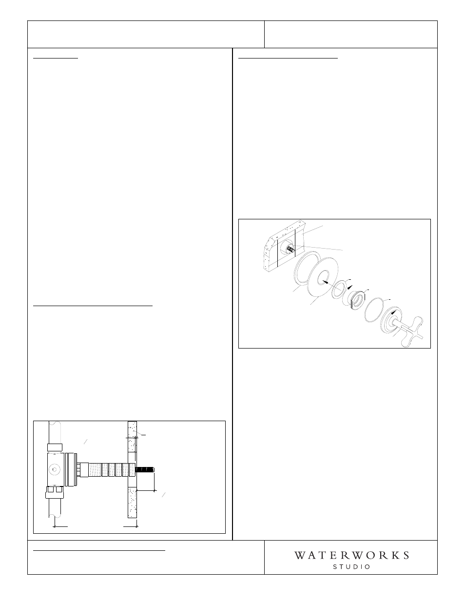
TRIM PLATE INSTALLATION:
¾ See Figure 2 for Steps 4-6.
4. After the proper cuts have been made, slide the
DIVERTER PLATE over the modified diverter valve
components and hold to finished wall, making sure
FOAM GASKET is behind it.
5. While holding DIVERTER PLATE against the finished
wall, thread & tighten TRIM ADAPTER onto the
THREADED TUBE, making sure the RED FIBER
WASHER is between DIVERTER PLATE and TRIM
ADAPTER.
6. With the correct orientation, thread the HANDLE
ASSEMBLY onto the TRIM CONNECTOR making
sure the O-RING is between the escutcheon and
DIVERTER PLATE. Note: The escutcheon is used to
tighten handle assembly.
Figure 2
FINISHED WALL
DIVERTER PLATE
FOAM GASKET
DIVERTER VALVE
THREADED TUBE
& CARTRIDGE STEM
[SOLD SEPARATELY]
RED FIBER WASHER
TRIM ADAPTER
O-RING
HANDLE ASSEMBLY
¾ If further assistance is required, please contact
Product Support at 1-800-927-2120 (8am-6pm EST).
- Ludlow Three Way Diverter Trim for Thermostatic System with Cross Handle Ludlow Three Way Diverter Trim for Pressure Balance System with Lever Handle Ludlow Three Way Diverter Trim for Pressure Balance System with Cross Handle Ludlow Two Way Diverter Trim for Thermostatic System with Lever Handle Ludlow Two Way Diverter Trim for Thermostatic System with Cross Handle Ludlow Two Way Diverter Trim for Pressure Balance System with Lever Handle Ludlow Two Way Diverter Trim for Pressure Balance System with Cross Handle