Installation guidelines, Rw atlas – Waterworks R.W. Atlas Volume Control Valve Trim with Metal Lever Handle User Manual
Page 2
PRODUCT SUPPORT 800.927.2120 8am - 6pm EST
RW ATLAS
Volume Control Valve Trim
INSTALLATION GUIDELINES
Page 2 of 2
11.21.2012
These guidelines have been prepared for the professional contractor to aid in the installation of:
RW ATLAS VOLUME CONTROL VALVE TRIM WITH METAL WHEEL HANDLE (STYLE# RWVC01) &
METAL LEVER HANDLE (STYLE # RWVC10)
All dimensions are based on original specification and are subject to change and variation.
Please consult your Design Associate for current specifications.
SEE SERVICE PART DOCUMENT FOR PART ORDERING, AVAILABLE ON WATERWORKS.COM
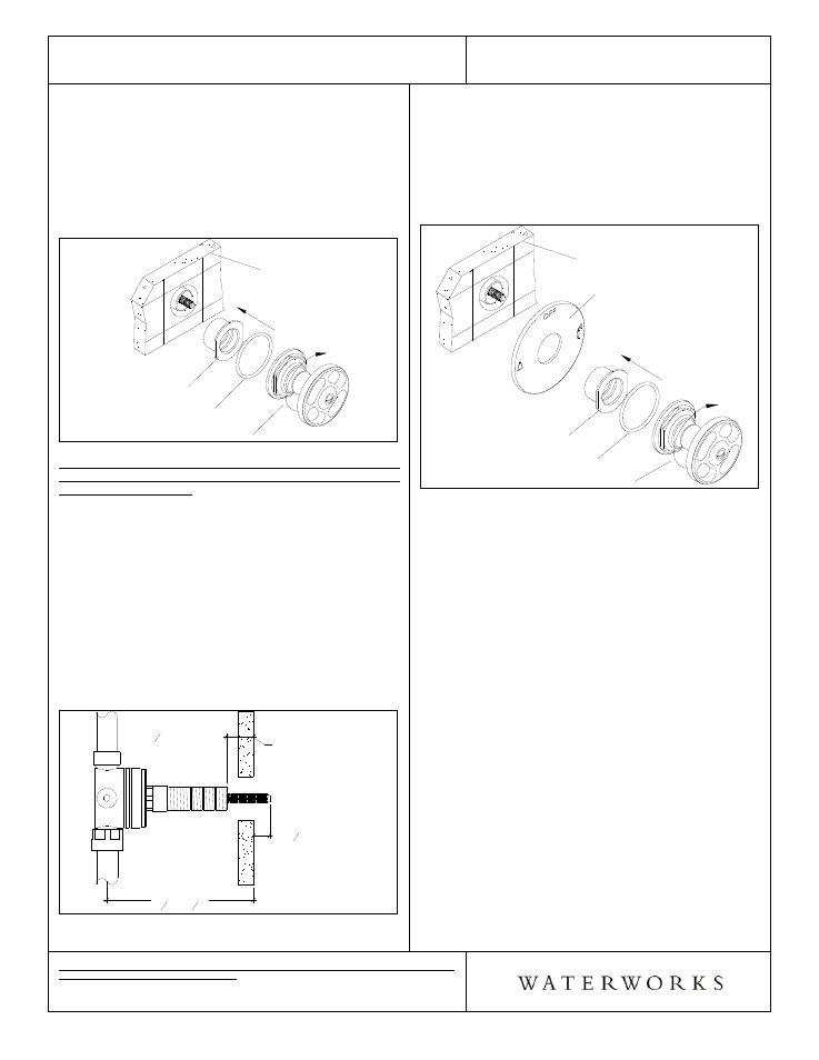
¾ See Figure - 02 for steps 4 & 5
4. Thread the trim nut to the threaded sleeve until they
stop at the finished wall.
5. Install handle assembly by threading it into the trim
adapter, making sure the o-ring is behind the
escutcheon. Use the handle's knurled piece to get a
good grip.
Figure - 02
TRIM ADAPTER
HANDLE O-RING
HANDLE ASSEMBLY
FINISHED WALL
CONTROL VALVE TRIM INSTALLATION WITH 2- WAY
or 3-WAY DIVERTER CONTROL VALVES
GUDV14R/23R/65/66:
¾ See Figure - 03 for steps 6 & 7
6. Pull the tile guard off the threaded sleeve on the
diverter valve rough. Mark the threaded sleeve at
the finished wall. Unthread the sleeve and cut 3/8"
behind the mark.
7. Mark the cartridge stems at the wall, then unthread
the cartridge from the valve body. Cut the cartridge
stems 3/8" in front of the mark.
8. After the cuts have been made, thread cartridge and
handles sleeves back onto valve body.
Figure - 03
ROUGH-IN
3
1
4
" - 4
1
4
"
FINISHED WALL
CUT SLEEVE
3
8
" FROM
FINISHED WALL
CUT STEM*
3
8
" FROM
FINISHED WALL
¾ See Figure - 04 for steps 9 & 10
9. Hold the diverter plate† (SOLD SEPARATELY) up to
wall and thread the trim nut onto the threaded
sleeve until it stops and secures the plate to the wall.
10. Install handle assembly by threading it into the trim
adapter, making sure the o-ring is behind the
escutcheon. Use the handle's knurled piece to get a
good grip.
Figure - 04
TRIM ADAPTER
HANDLE O-RING
HANDLE ASSEMBLY
FINISHED WALL
DIVERTER PLATE
†
*
If required, a 1" stem extension is available.
Style No. 890831
Item
No.
29-72873-53591
†
GUDV14 requires the 2-Way Thermostatic Diverter
Valve Trim (Plate Only): STYLE No. UNDV00
†
GUDV23 requires the 2-Way Pressure Balance
Diverter Valve Trim (Plate Only): STYLE No. UNDV10
¾ If further assistance is required, please contact
Product Support at 1-800-927-2120 (8am-6pm EST).
¾ See service part document for parts ordering,
available on WATERWORKS.COM.