Waterworks Formwork Volume Control Valve Trim with Metal Lever Handle User Manual
Installation guidelines
PRODUCT SUPPORT 800.927.2120 8am - 6pm EST
FORMWORK
Volume Control Valve Trim
Installation Guidelines
Page 1 of 2
Rev - 01
4.7.2014
These guidelines have been prepared for the professional contractor to aid in the installation of:
FORMWORK VOLUME CONTROL VALVE TRIM WITH METAL KNOB HANDLES (STYLE No. FMVC01) &
FORMWORK VOLUME CONTROL VALVE TRIM WITH METAL LEVER HANDLES (STYLE No. FMVC10)
All dimensions are based on original specification and are subject to change and variation.
Please consult your Design Associate for current specifications.
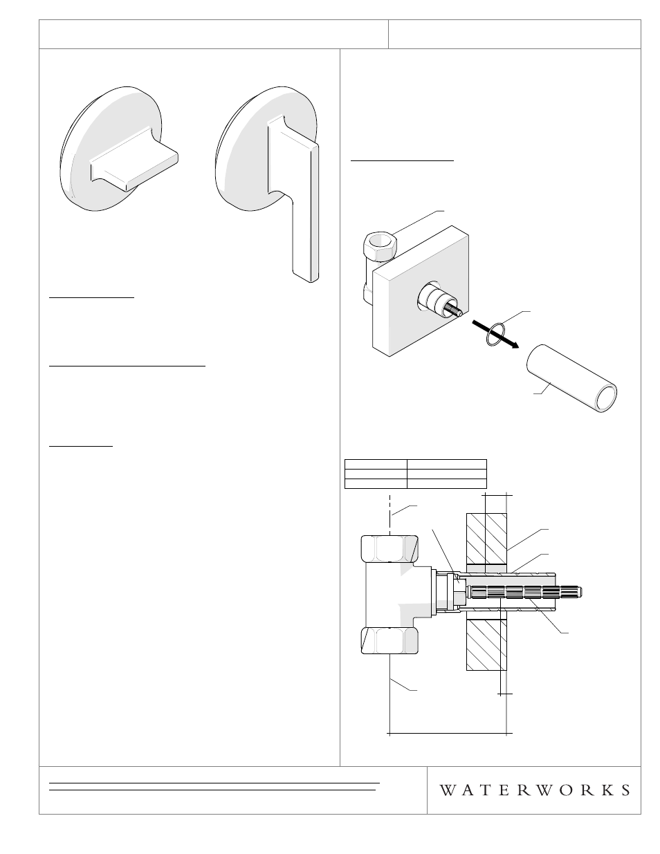
STYLE No. FMVC01
STYLE No. FMVC10
with Metal Knob Handle
with Metal Lever Handle
SPECIFICATIONS:
Control Valve Rough-in Depth Min: 3-1/8"
Control Valve Rough-in Depth Max: 4-3/4"
Fittings Hole Diameter: Ø1-3/8"
REQUIRED PLUMBING DETAILS:
Universal 3/4" Volume Control Valve
STYLE No. GUVC16 (Hot Cartridge)
Universal 3/4" Volume Control Valve
STYLE
No. GUVC17 (Cold Cartridge)
IMPORTANT:
¾ To ensure this product is installed properly, you must
read and follow these guidelines. The owner/user of
this product must keep this information for future
reference.
¾ This product must be on-site prior to rough-in. This
allows the installer to visualize the installation and
verify the center spread.
¾ This product must be installed by a professional
licensed contractor. Be sure your installation conforms
to all federal, state, and local codes. In the State of
Massachusetts, all installations must comply with the
rules and regulations set forth within 248 CMR.
¾ Wall valves (SOLD SEPARATELY) control on, off and
volume and must be installed for each fitting that will
have water flowing to it. If using a wall valve with the
Universal 3/4" Thermostatic Valve (Style No.
GUTH37R - SOLD SEPARATELY), refer to the
Installation Guidelines for the Thermostatic Valve
which contains related installation information.
¾ Refer to the specification and assembly drawings
attached. Product is sold partially assembled but
shown fully disassembled for illustrative and service
purposes only.
¾ Inspect the product to ensure you have all the parts
required for proper installation. Use only a strap
wrench or protected/smooth-jaw wrench on any
finished surface.
¾ DO NOT use putty. Putty contains oil and can cause
permanent discoloration on certain materials such as
marble, granite and any porous surface.
TRIM INSTALLATION:
1. Remove the TILE GUARD and the O-RING from the
VALVE as shown in Figure - 01.
FIGURE - 01
¾ See Figure - 02 for steps 2 & 3
DIMENSION VALUE
(INCHES)
A 1/2"
B 1/16"
FIGURE - 02
VALVE
O-RING
TILE GUARD
VALVE
O-RING
TILE GUARD
THREADED
TUBE
FINISHED WALL
CENTER OF
INLET
CENTER OF
INLET
CARTRIDGE
STEM
CARTRIDGE
"A"
CUT THREADED TUBE
BEHIND FINISHED WALL
"B"
CUT CARTRIDGE STEM
BEHIND FINISHED WALL
ROUGH-IN DEPTH
THREADED
TUBE
FINISHED WALL
CENTER OF
INLET
CENTER OF
INLET
CARTRIDGE
STEM
CARTRIDGE