Installation guidelines – Waterworks Formwork Pressure Balance Control Valve Trim with Metal Lever Handle User Manual
Page 3
PRODUCT SUPPORT 800.927.2120 8am - 6pm EST
FORMWORK
Pressure Balance Control Valve Trim with Metal Lever Handle
Installation Guidelines
Page 3 of 3
Rev - 01
4.30.2014
These guidelines have been prepared for the professional contractor to aid in the installation of:
FORMWORK PRESSURE BALANCE CONTROL VALVE TRIM WITH METAL LEVER HANDLE (STYLE No. FMPB10)
All dimensions are based on original specification and are subject to change and variation.
Please consult your Design Associate for current specifications.
8. Turn the HANDLE until it stops and using a
thermometer, verify that the temperature is the same
as the temperature set in Step 4. If the temperature is
not the same repeat the calibration process.
¾ If further assistance is required, please contact Product
Support at 1-800-927-2120 Ext 2 Monday through
Friday, 8am - 6pm EST.
¾ See the service part document for parts ordering,
available on WATERWORKS.COM.
* Putty contains oil and can cause permanent
discoloration on certain materials such as marble,
granite and any porous surface.
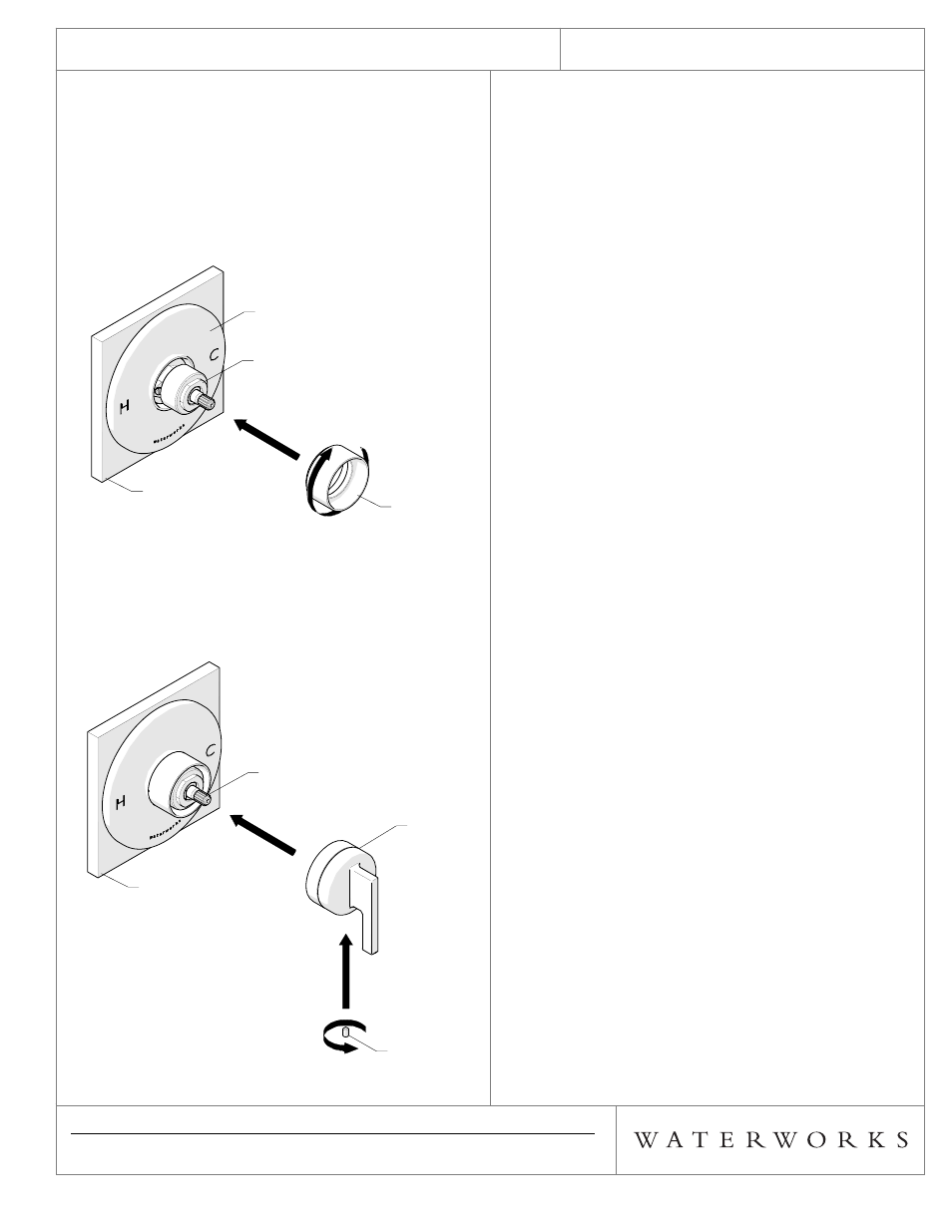
6. Hold the TRIM PLATE against the finished wall then
thread the RETAINING COLLAR onto the GLAND
COVER as shown in Figure - 06. Securely tighten the
RETAINING COLLAR to hold the TRIM PLATE against
the finished wall.
¾ NOTE: A GASKET for the TRIM PLATE is provided. If
desired, a bead of caulk or a clear silicone may be
applied where the TRIM PLATE contacts the finished
wall. DO NOT use putty.*
FIGURE - 06
7. With the VALVE turned off, place the HANDLE on the
VALVE STEM in the 6 o'clock position then tighten the
SET SCREW to secure the HANDLE as shown in
Figure - 07
FIGURE - 07
TRIM PLATE
FINISHED
WALL
GLAND COVER
RETAINING
COLLAR
TRIM PLATE
FINISHED
WALL
GLAND COVER
RETAINING
COLLAR
FINISHED
WALL
VALVE STEM
SET SCREW
HANDLE
FINISHED
WALL
VALVE STEM
SET SCREW
HANDLE