Waterworks Boulevard Volume Control Valve Trim with Metal Lever Handles User Manual
Installation guidelines
Boulevard Lever Handle Wall Valve And Trim
11/02
W A T E R W O R K S
These guidelines have been prepared for the professional contractor to aid in the installation of:
BOULEVARD LEVER HANDLE WALL VALVE AND TRIM
(GUSV12R & BDSV48)
All dimensions are based on original specifications and are subject to change and variation.
Please consult your Design Associate for current specifications.
Installation Guidelines
1
NOTES:
➢ Use only a protected, smooth-jawed, or strap wrench on any finished
surface.
ROUGH-IN:
➢ Install the valve with the water flowing in the direction indicated.
➢ IMPORTANT:Valve rough-in is 2
1
⁄
2
" from the centerline of the supplies
to the face of the finished wall.
➢ Separate supply stop valves, which will facilitate servicing should be
installed in an accessible location.
FINISH:
➢ Screw on trim and measure from the base of the escutcheon to the
finished wall. Remove the trim and retain this measurement.
➢ Cut the valve stem and threaded sleeve so that the trim becomes flush
with the finished wall.
➢ The amount cut from the valve stem and threaded sleeve should be the
same as the distance measured in the previous step.
➢ Reattach the trim and check to ensure it is flush with the finished wall. If
necessary, cut the valve stem and threaded sleeve further to make flush.
➢ Carefully turn on the water supply and check all connections for leaks.
➢ If further assistance is required, please contact Product Support at
1-800-927-2120 (8am-7pm EST).
2
1
⁄
2
"
2
1
⁄
2
"
2
11
⁄
16
"
2
1
⁄
8
"
11
⁄1
6
"
1
⁄
2
"
Note:
3
⁄
4
" NPT
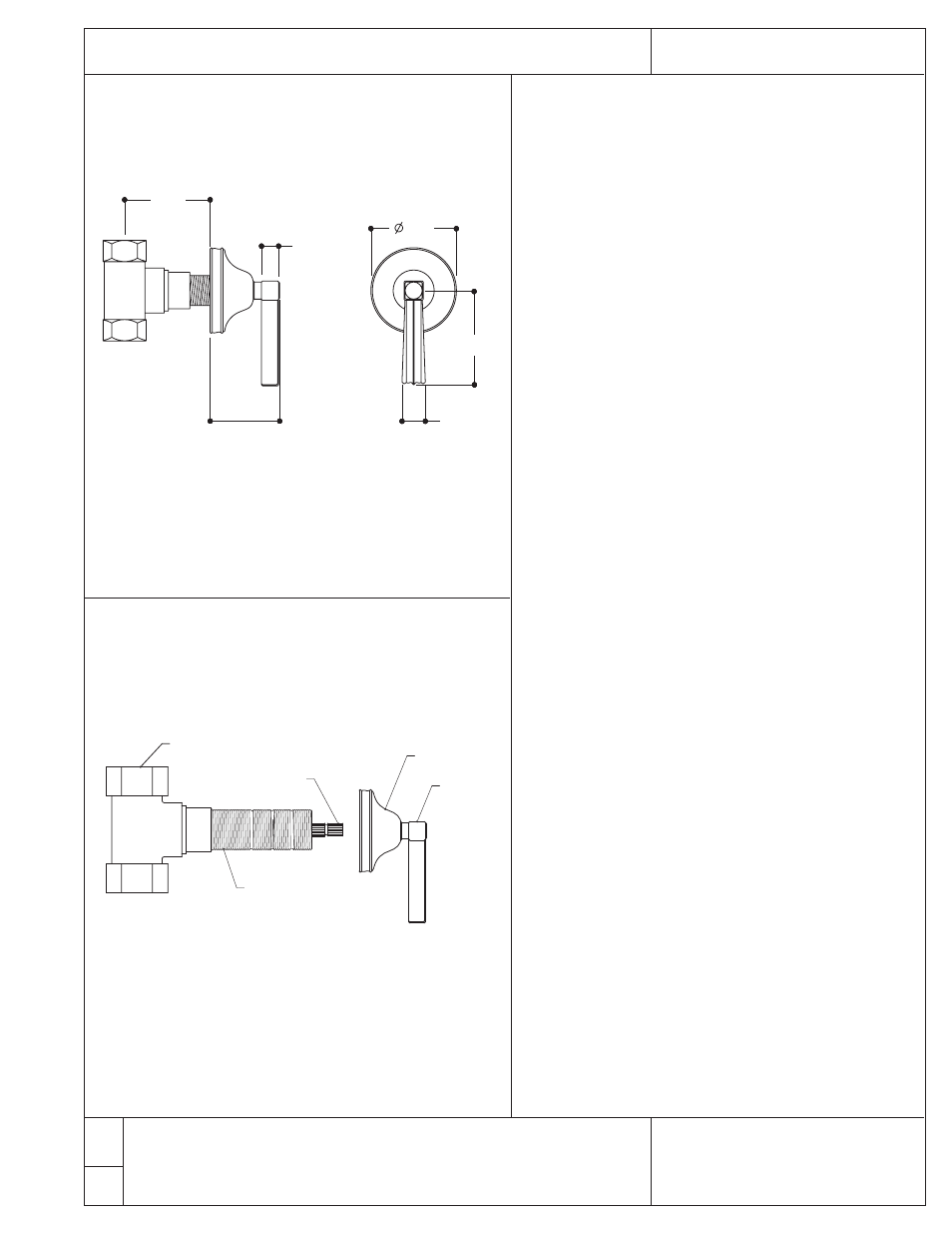
GUSV12R (rough) & BDSV48 (trim)
Escutcheon
Handle
Valve
Threaded Sleeve
Valve Stem
Figure 1