Waterworks .25 Volume Control Valve Trim with Metal Lever Handle User Manual
Installation guidelines, 25 wall valve trim
Installation Guidelines
W A T E R W O R K S
Waterworks is a registered trademark of Waterworks Inc.
04.11.07
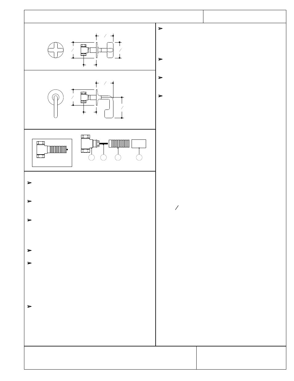
PTSV47 (trim) & GUSV16R (rough)
PTSV48 (trim) & GUSV16R/17R (rough)
2
1
2
"
2
3
8
"Ш
2
3
8
"
3
1
8
"
2
1
2
"
2
3
8
"Ш
.25 Wall Valve Trim
FIGURE 1
1
2
3
4
IMPORTANT
To ensure this product is installed properly, you
must read and follow these guidelines.
The owner/user of the valve must keep this
information for future reference.
Valve body rough-in depth is 3" from the centerline
of the inlets to the face of the finished wall. The
valve must be installed according to the flow direction
arrow marked on the side of the wall valve body.
Be sure your installation conforms to local codes.
Wall valves control on/off/volume and must be
installed for each fitting that will have water flowing to
it. If using a wall valve with our thermostatic valve,
refer to the Installation Guidelines for the
Thermostatic Valve which contains related installation
information.
Refer to the specification and assembly drawings
attached. Shower trim and valves are sold partially
assembled but shown fully disassembled for illustrative
and service purposes only.
This valve should be on-site prior to rough in and
allows the installer to visualize the installation.
Inspect this product to assure you have all parts
required for proper installation.
Use only a strap wrench or protected/smooth-jaw
wrench on any finished surface.
ROUGH IN:
REQUIRED: Ideal valve body rough-in depth is 3" from
the centerline of the inlets to the face of the finished
wall.
1. Remove the tile shield (4) and unthread the threaded
sleeve (3) from the valve body assembly (1,2).
2. If soldering any connections, remove the cartridge (2)
to prevent damage to seals.
3. For each fitting that will have water flowing to it, install
a wall valve according to the flow direction arrow
marked on the side of the wall valve body.
4. Run
3
4
" copper supply lines to the proper height of the
valve inlets and be sure to secure all piping and fittings.
Install the valve at a height and spread (if applicable)
that is comfortable to the user.
5. Reinstall the cartridge and threaded sleeve making sure
the tile shield is attached.
6. Turn on the supplies and check for leaks.
ATTACH THE TRIM:
7. Pull the tile shield (4) off the threaded sleeve (3).
8. Thread the handle trim connector onto the handle.
This product must be installed by a professional
contractor.
9. Thread the handle trim connector and handle onto
the threaded trim sleeve (3).
These guidelines have been prepared for the professional contractor to aid in the installation of:
.25 WALL VALVE TRIM WITH CROSS HANDLE (PTSV47) & LEVER HANDLE (PTSV48)
All dimensions are based on original specification and are subject to change and variation. Please consult
your Design Associate for current specifications.
3"
3"