Installation guidelines, Henry – Waterworks Henry Three Hole Gooseneck Kitchen Faucet, Metal Lever Handles and Spray User Manual
Page 2
PRODUCT SUPPORT 800.927.2120 8am - 6pm EST
HENRY
Three Hole Gooseneck Kitchen Faucet and Spray
INSTALLATION GUIDELINES
Page 2 of 3
10.14.2014
These guidelines have been prepared for the professional contractor to aid in the installation of:
HENRY THREE HOLE KITCHEN FAUCET WITH SPRAY. STYLE NOS.
HNKM20 & HNKM30
All dimensions are based on original specification and are subject to change and variation.
Please consult your Design Associate for current specifications.
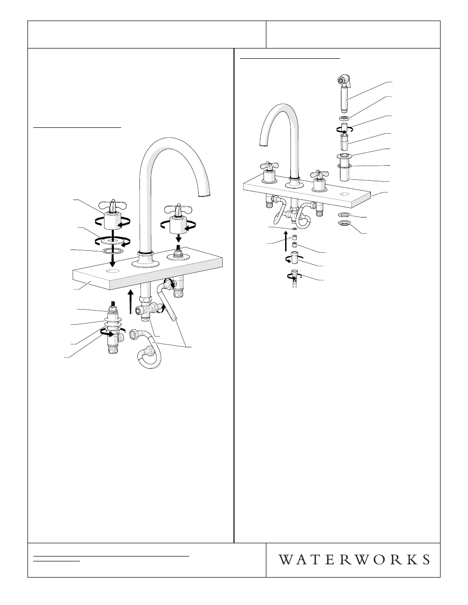
SIDE SPRAY INSTALLATION:
¾ See Figure 3. for Steps 10-16.
KNURLED HOSE END
CHECK VALVE HOUSING
FLOW RESTRICTING
CHECK VALVE
CHECK
VALVE
RUBBER
GASKET
MOUNTING
DECK
LOWER
RUBBER
WASHER
NUT
SHANK
UPPER
RUBBER
WASHER
ESCUTCHEON
PLASTIC
SLEEVE
CONICAL
HOSE
END
RETAINING
COLLAR
SPRAY
KNURLED HOSE END
CHECK VALVE HOUSING
FLOW RESTRICTING
CHECK VALVE
CHECK
VALVE
RUBBER
GASKET
MOUNTING
DECK
LOWER
RUBBER
WASHER
NUT
SHANK
UPPER
RUBBER
WASHER
ESCUTCHEON
PLASTIC
SLEEVE
CONICAL
HOSE
END
RETAINING
COLLAR
SPRAY
FIGURE - 03
¾ Note: HOSE is not shown complete.
10. Remove the NUT & LOWER RUBBER WASHER from
bottom of SHANK
11. Place ESCUTCHEON & SHANK through the
mounting hole, making sure the UPPER RUBBER
GASKET is below. Reinstall the NUT and LOWER
RUBBER WASHER to secure the spray return.
12. Drop the KNURLED END of the handshower HOSE
through the ESCUTCHEON and below the deck.
13. Spread the PLASTIC SLEEVE open and place the
HOSE into it. Snap the PLASTIC INSERT into the
ESCUTCHEON to make sure HOSE does not slip
below the deck.
14. Thread the RETAINING COLLAR onto the top of the
ESCUTCHEON.
15. Connect the CHECK VALVE HOUSING to the
bottom of the TEE, making sure the RUBBER
GASKET is between. Note: The FLOW RESTRICTING
CHECK VALVE and CHECK VALVE are in the
housing.
16. Lastly attach the KNURLED END of the HOSE to the
CHECK VALVE HOUSING and attach the CONICAL
END of the HOSE to the SPRAY.
3. Reinstall the RUBBER WASHER and NUT to the
bottom of the SHANKS to secure the SPOUT
ASSEMBLY.
4. Reinstall the DIVERTER TEE to the SHANK, making
sure the TEE RUBBER WASHER is between. Note:
There are 2 FILTER SCREENS on the inlets of the
DIVERTER TEE.
HANDLE INSTALLATION:
¾ See Figure 2. for Steps 5-9.
TEE
HOSE
ASSEMBLY
NUT
VALVE BODY
PLASTIC
WASHER
LOWER
RUBBER
WASHER
ESCUTCHEON
UPPER
RUBBER
WASHER
HANDLE
ASSEMBLY
MOUNTING
DECK
TEE
HOSE
ASSEMBLY
NUT
VALVE BODY
PLASTIC
WASHER
LOWER
RUBBER
WASHER
ESCUTCHEON
UPPER
RUBBER
WASHER
HANDLE
ASSEMBLY
MOUNTING
DECK
FIGURE - 02
5. Remove the HANDLE ASSEMBLY, ESCUTCHEON &
UPPER RUBBER WASHER from the VALVE BODY.
6. Thread the NUT all the way down the VALVE BODY
and then place the VALVE BODY through the hole
from the underside of the MOUNTING DECK.
7. Thread the ESCUTCHEON onto the VALVE BODY,
making sure the UPPER RUBBER WASHER is
underneath the ESCUTCHEON. The ESCUTCHEON
will thread onto the VALVE BODY until it comes to a
stop; DO NOT over tighten.
8. Thread the HANDLE ASSEMBLY onto the VALVE
BODY. Verify the handle alignment, then tighten the
NUT to secure.
9. Connect the HOSE ASSEMBLY to the TEE and to the
VALVE BODY. Repeat Steps 5-9 to install other
handle.