0 mounting plate installation and setup, 1 unpacking and assembly, 2 enclosure disassembly – Rice Lake SURVIVOR LaserLight Series Stop/Go Remote Displays - Installation & Operation Manual User Manual
Page 8: Mounting plate installation and setup, 1 unpacking and assembly 2.2 enclosure disassembly
4
LaserLight Installation and Operation Manual
2.0
Mounting Plate Installation and Setup
The LaserLight remote display can be easily set up and configured once mounted to a wall or pole. This section
describes basic installation, AC wiring, RS-232, RS-485, and 20 mA current loop connections. Once installation
setup is complete, go to Section 3.0 for information on configuring the remote display.
Use a wrist strap to ground yourself and protect components from electrostatic discharge (ESD) when
working inside the enclosure.
This unit uses double pole/neutral fusing which could create an electric shock hazard. Procedures
requiring work inside the remote display must be performed by qualified service personnel only.
The
LaserLight
has no on/off switch. before opening the unit, ensure the power cord is disconnected
from the power outlet.
2.1
Unpacking and Assembly
Immediately after unpacking, visually inspect the LaserLight remote display for damage. If any parts were
damaged in shipment, notify Rice Lake Weighing Systems and the shipper immediately. The shipping carton
contains the remote display and this manual. The main components of the LaserLight remote display include:
•
Painted steel enclosure
•
Primary and secondary display boards
•
Power supply
•
Mounting panel for the CPU board (located on back of mounting plate)
Remove the protective plastic on the lens of the LaserLight as it will obscure the display over time and
become very difficult to remove later on.
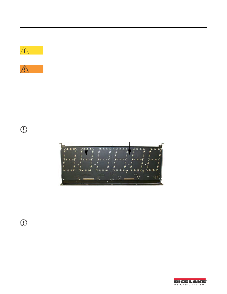
Figure 2-1. Mounting Plate Showing Primary / Secondary Display Boards (7-Segment Display)
2.2
Enclosure Disassembly
For ease of installation, remove the mounting plate (which includes the primary and secondary display boards)
before installing the LaserLight remote display. This protects the LEDs from unnecessary jarring and makes the
enclosure lighter for installation. Use the following steps to remove the mounting plate from the enclosure.
Use caution when lowering or raising the mounting plate to ensure the LEDs do not touch the enclosure
sides.
1. Remove the captive screws located on the bottom of the enclosure. The mounting plate is located on the
inside of the enclosure. It is mounted on a frame that can be held in place by tabs and two pins, (located on
the inside of the enclosure, shown in Figure 2-2).
2. Glide the mounting plate frame downward so that it hangs freely beneath the enclosure.
3. Disconnect the chassis ground wire from the top of the mounting plate mounting frame.
4. Disconnect the AC cord assembly from the power supply.
5. Using a slight diagonal twisting motion, slide the mounting plate out from the inside of the enclosure and
set it aside.
CAUTION
WARNING
Important
Primary display
Secondary display
Important