Rice Lake SURVIVOR LaserLight Series Stop/Go Remote Displays - Installation & Operation Manual User Manual
Page 25
Configuration
21
3.7.2
Set or Get the Digital I/O (7 Segment with Stop/Go Light)
Version 2.05 only accepts the serial digital I/O commands listed in this manual. All previous serial digital I/O
commands prior to Version 2.05 will not work properly with this product.
The digital outputs are set to High (OFF) on reset.
Table 3-8. Serial Commands (Basic Configuration)
To use the two Digital Inputs and Digital Outputs, use J1 (See Figure 2-8 8) to connect and use the following
message command formats to set or get the Digital I/O
Set Relay (set relay output 1 off)
|00SR1OFF!
Response: OK = success (State: DO1_+5V) or ?? = error
Get Digital (input) 0
|00GRO!
Response: ON = gnd or OFF = +5V
Get Digital input levels (all digin)
|00DI!
Response: 0 = LL, 1 = LH 2 = HL, 3 = HH
Set Digital output levels to HH (all digout = +5V)
|00DO3!
Response: OK = success (states: DO0=DO1=+5V) or ?? = error
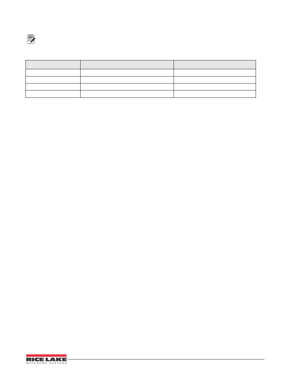
Traffic Light State
Dry Contact
Serial Commands
Stop
Dig0 and Dig1 open circuit
|00DO3!
Green Circle
Dig0 open circuit; Dig1 pulled low
|00DO2!
Green Arrow
Dig0 pulled low; Dig1 open circuit
|00DO1!
Off
Dig0 and Dig1 pulled low
|00DO0!
Note