0 configuration, 1 auto-learn, 2 manual configuration – Rice Lake SURVIVOR LaserLight Series Stop/Go Remote Displays - Installation & Operation Manual User Manual
Page 14: Configuration, 1 auto-learn 3.2 manual configuration
10
LaserLight Installation and Operation Manual
3.0
Configuration
Once the LaserLight remote display is installed, it may need to be configured if your indicator requires special
settings. This can be done manually and is explained in Section 3.2.
Using Auto-Learn (Section 3.1) simplifies installation by automatically detecting the communications format and
data rate used by the indicator and eliminates the need for configuration.
3.1
Auto-Learn
The LaserLight remote display incorporates a software feature called Auto-Learn. Auto-Learn examines the serial
data stream sent from the attached indicator and attempts to determine the data settings and format used by the
indicator.
Auto-Learn occurs automatically when Port 0 is not locked via software configuration (not locked by default)
(Table 3-5), and the connecting indicator is configured to send continuous (streaming) data. It will also occur
automatically if the currently streamed format changes. LaserLight will Auto-Learn by itself in most cases. Or, you
can force this by pressing the external Auto-Learn button.
Use the following quick steps for Auto-Learn.
1. Open the enclosure per disassembly instructions in Section 2.2 on page 4 and connect the serial interface.
2. Visually inspect that the Auto-Learn button is connected to J5 on the CPU board (see Figure 3-1 for
plug-in location).
3. Power up the remote display.
4. Momentarily press the Learn button.
5. Use the right and left buttons to shift the displayed data string if the displayed weight is not positioned with
LSD.
If you are using an indicator with a Toledo T8142 format, follow steps 1 through 5 and then go to SP IND in the
serial menu. Select 1 under special indicators.
It is recommended to lock Port 0 (see Table 3-5), to eliminate any un-intentional changes from occurring.
3.2
Manual Configuration
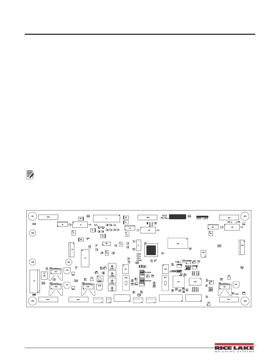
To begin configuration, open the enclosure (See Section 2.2 on page 4 for enclosure disassembly instructions), to
access the CPU board (Figure 3-1) and digit display board (Figure 3-2).
Figure 3-1. LaserLight CPU Board
Note
J9
J8
J6
J5
J7
J4
ISP