1 display, 2 digital outputs, 3 digital inputs – Rice Lake SURVIVOR LaserLight Series Stop/Go Remote Displays - Installation & Operation Manual User Manual
Page 22: 4 loop back, 5 version, Display, Digital outputs, Digital inputs, Loop back
18
LaserLight Installation and Operation Manual
3.4.1
Display
When this feature is enabled, all LEDs remain lit until the
ENTER
button is pressed (Figure 3-2 11).
3.4.2
Digital Outputs
When enabled, this feature provides a way to view the different states of the digital outputs or the stop/go option if
installed.Use left and right arrows to increment/decrement and display the states LL, LH, HL, and HH which are
digital values of the 2 ports.
The following table lists the relay terminology and digital signal level terminology of each command.
Press the right button again to display LL and the stop/go option will show no light at all.
Press the right button again to display LH and the stop/go option will show a green arrow.
Press the right button again to display HL and the stop/go option will show a green circle.
So when HH is selected, the stop/go option will show a red circle.
3.4.3
Digital Inputs
When enabled, the digital inputs displays the current values read from the digital inputs.
3.4.4
Loop Back
When enabled, this feature provides a loop-back self test for use in diagnosing serial communications errors. The
loop-back self test checks the function of the remote display serial port by sending and receiving data to itself. The
following table shows the required connections.
If Port 1 receives nothing from Port 0 for three seconds, the following message is displayed on the remote display:
Fail 1
If Port 0 receives nothing from Port 1 for three seconds, the following message is displayed on the remote display:
Fail 2
If communications are successful between the two, the following message is displayed:
Pass
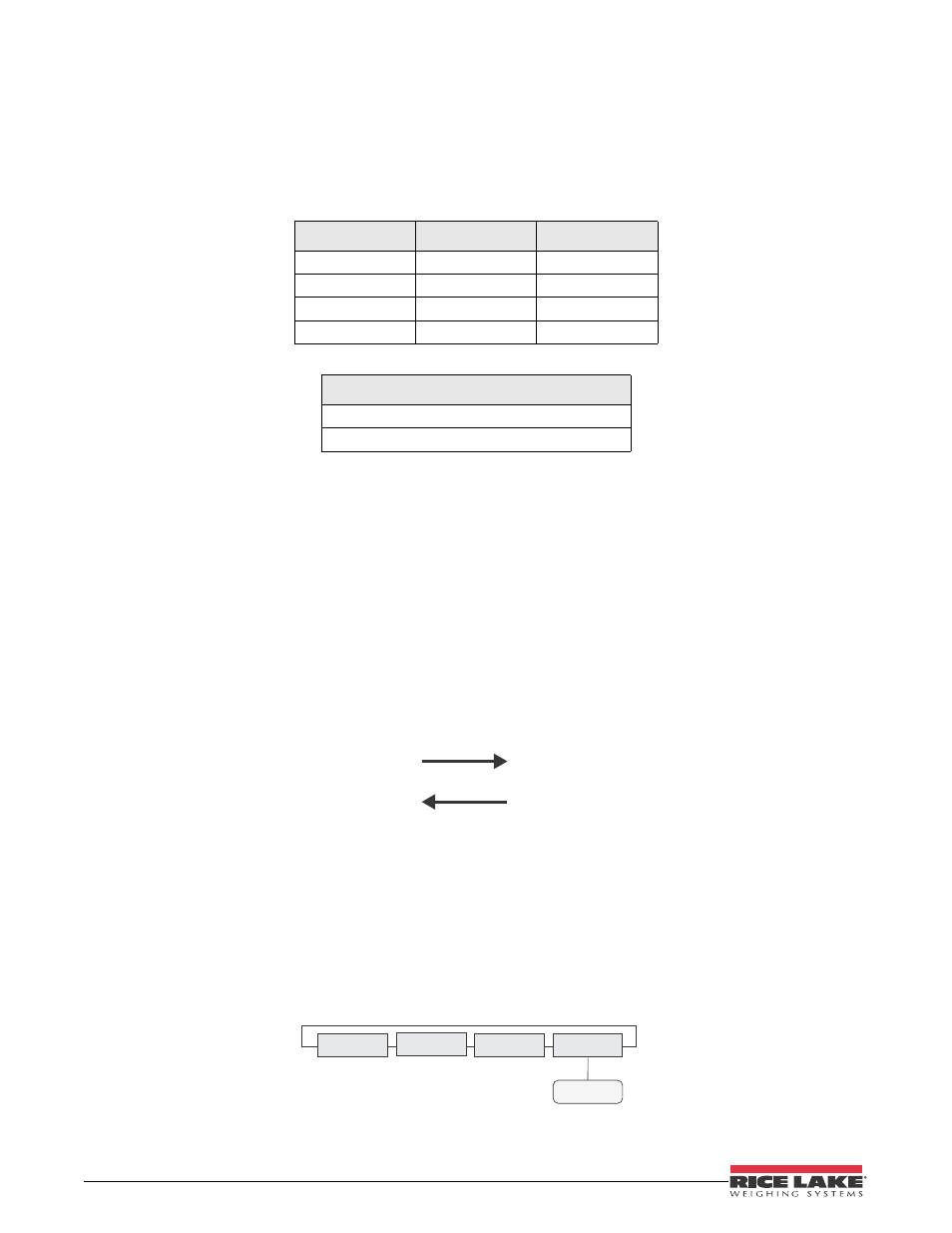
3.5
Version
When
Version
is selected from the main menu choices (Figure 3-8), the current software version is shown on the
remote display.
Figure 3-8. Version Menu
Dig Out 1
Dig Out 0
Stop/Go Signal
L
L
Off
L
H
Green Arrow On
H
L
Green Circle On
H
H
Red Stop
Relay On/Off Terminology
L = ON = 0V
H = OFF = +5V
Table 3-7.
Port 0 TR
Port 1 RCV
Port 1 TR
Port 0 RCV
VERSION
CONFIG
SERIAL
TEST
VER