6 demand print displaying, 7 serial commands, 6 demand print displaying 3.7 serial commands – Rice Lake SURVIVOR LaserLight Series Stop/Go Remote Displays - Installation & Operation Manual User Manual
Page 23
Configuration
19
3.6
Demand Print Displaying
The indicator and the LaserLight remote display can be set up to do a demand print display for such applications as
cattle weighing. This is useful if you want to show and keep the last weight of an animal.
Demand print display can be set up using Auto-Learn when the Port 0,
Hold Weight
parameter is turned
On
, and it is
set up manually by formatting the baud rate, data bits, parity, etc. of the remote display and the indicator.
Using Auto-Learn, ensure
HOLD WT
is on and continuously push the print button on the indicator to attempt a
demand print display.
3.7
Serial Commands
The LaserLight remote display has the ability to receive commands, display messages, or use a digital I/O (2 inputs
& 2 outputs). When interfaced to an indicator having a configurable serial string like the IQ plus 355, 710, 800, or
810, the print ticket format can be configured to allow the user to use the
key to send a message that
temporarily interrupts the streamed weight display. The amount of time the message is displayed is defined by the
MSG TM
(message time) parameter under the
CONFIG
menu in the remote display, for the 7-segment remote display.
If the LaserLight remote display is interfaced with a programmable smart indicator like the 920i, a user program
can be written to allow the user to send messages utilizing softkeys or events. When sending messages from a user
program, the user can send one message to temporarily override the streamed weight display or send multiple
messages to be displayed one at a time for several seconds each, replacing the weight display all together if desired.
The remote display also accepts serial commands to return the current time and date or to set the time and date to a
new setting. This information can be used in conjunction with user programs in the 920i to ensure the indicator and
remote display have the same time and date settings.
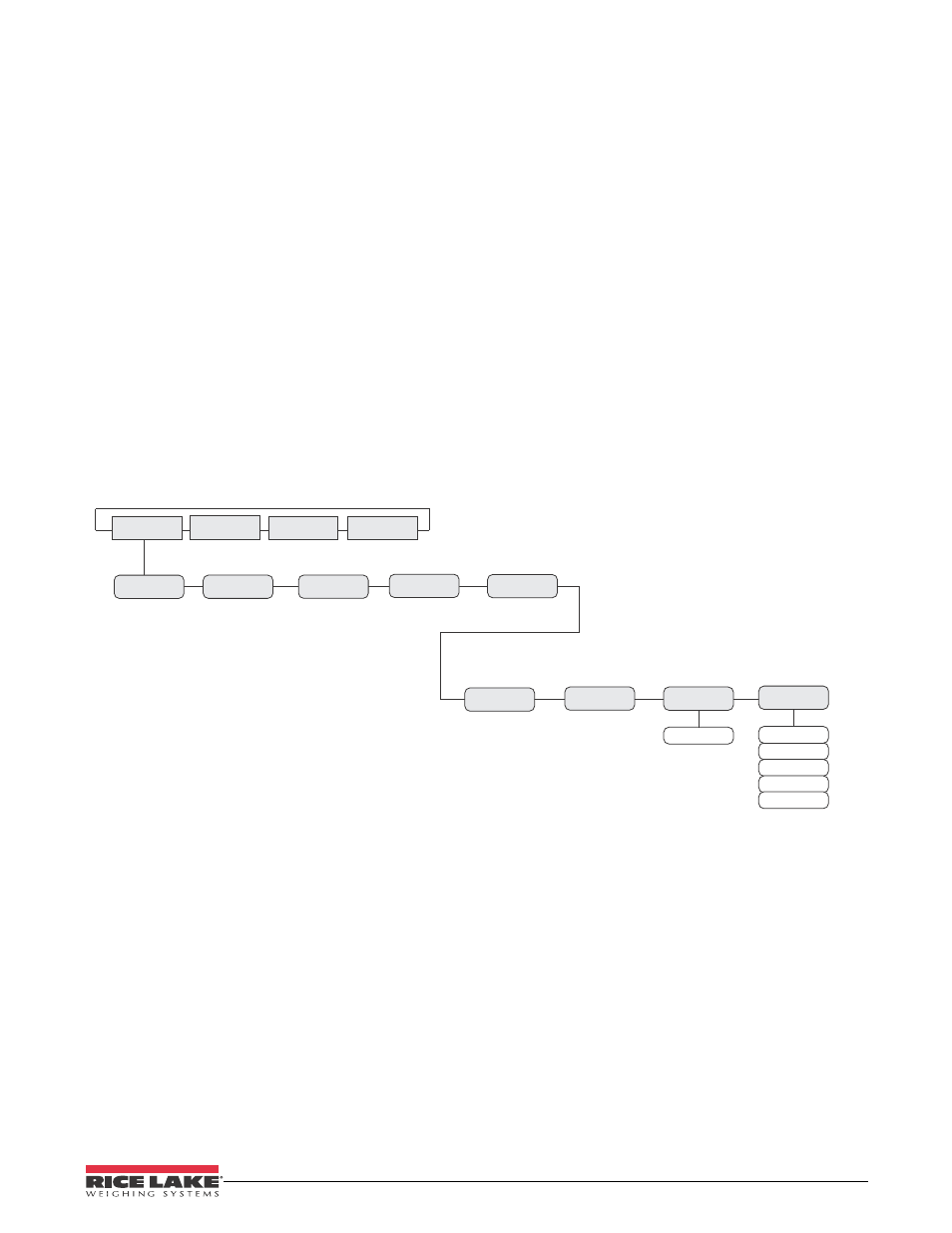
Figure 3-9. Assign Address and Message Timed
TIME/DATE
TEMP
BRIGHT
SUPP0
MIRROR
STDSTL
MSG TM
ADDRES
0 - 31
15 sec
5 sec
30 sec
1 min
5 min
TEMP ADJ
CONFIG
SERIAL
TEST
VER