5 traffic light option, 1 dry contact wiring, Dry contact wiring – Rice Lake SURVIVOR LaserLight Series Stop/Go Remote Displays - Installation & Operation Manual User Manual
Page 30
26
LaserLight Installation and Operation Manual
4.5
Traffic Light Option
The Laserlight 4-SG remote display also comes with a traffic light option that uses 4
"
display digits in the 6
"
enclosure. The traffic light is factory configured to be controlled with serial commands (as described in Section 3.7
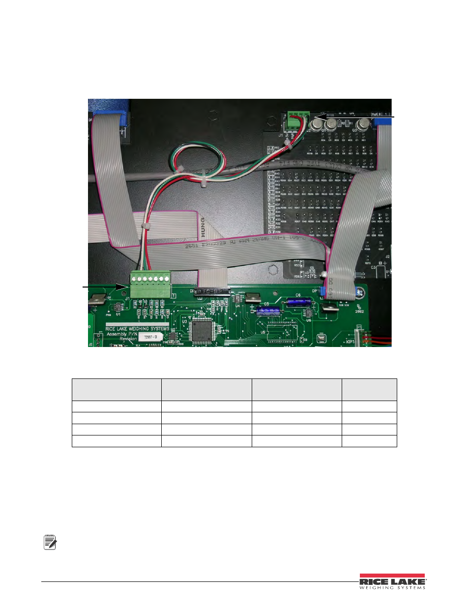
on page 20), but can be controlled by using dry contact switches: one switch or two switches. The following photo
illustrates the location of the traffic light board and the wiring for it and table 4-3 illustrates the wiring from the
traffic light board to J1 on the LaserLight CPU board.
Figure 4-4. Back of the LaserLight 4-SG Remote Display Showing CPU Board Location and Traffic Light Option
Wiring the traffic light board is explained below.
4.5.1
Dry Contact Wiring
The Dig 0 and Dig 1 pins on the traffic light board (pin 2 and pin 3 on connector J1 respectively) have pull up
resistors so that the operation of the traffic light can be controlled by switching the Dig 0 or Dig 1 (or both) to
ground.
A reset to the Laserlight CPU board will set the D0 and D1 pins on the Laserlight CPU (pins 5 and 6 on J1) to a
high pulled up state therefore, the default state of the traffic light will be a stop light (red).
Signal
Traffic Light Board
Location J1
Laserlight CPU Board
Location J1
Corresponding
Wire Color
5 VDC
1
4
Red
DIG O
2
5
Green
DIG 1
3
6
White
GND 4
7
Black
Table 4-3. Traffic Light Wiring
J1 Location
on the
Laserlight
CPU board
J1 location
on the traffic
light option
board
Note