Figure 2-8, Table 2-2 – Rice Lake SURVIVOR LaserLight Series Stop/Go Remote Displays - Installation & Operation Manual User Manual
Page 12
8
LaserLight Installation and Operation Manual
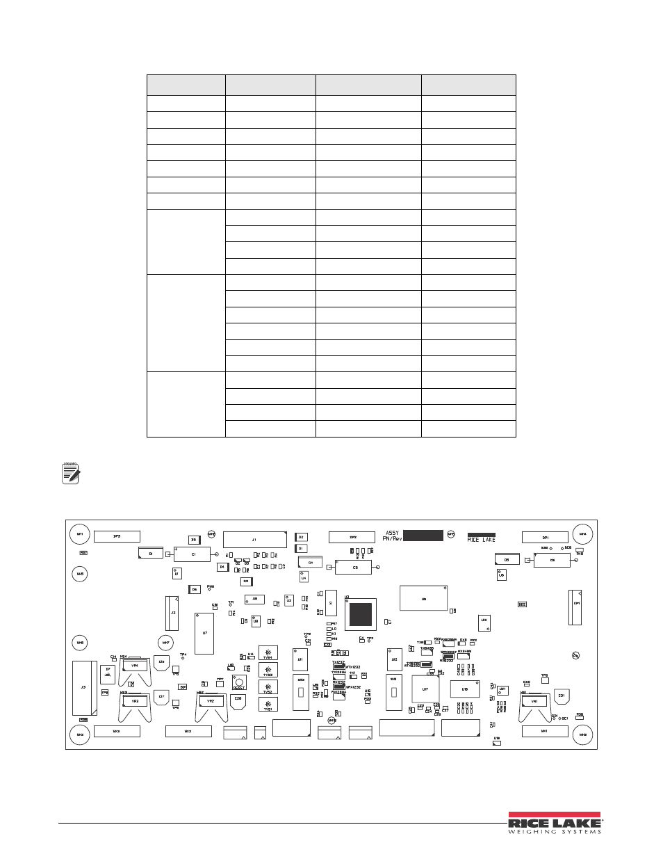
Terminals J6, J8, and J9 are removable screw terminal plugs.
Port 0 is used for input only and port 1 is used to drive the next LaserLight Remote Display. See Table 2-2
above.
Figure 2-8 shows the LaserLight remote display CPU board.
Figure 2-8. LaserLight Remote Display CPU Board
Port 0 which is connected to the indicator supports three configurations; 20 mA, RS-232, and RS-485
communications. Port 1 which is the Echo port, supports 20 mA and RS-232 communications.
Connector
Pin Assignment
Function
Port Position
J1
1
Ground
2
Digin 0
3
Digin 1
4
+ 5 Volts
5
DigOut 0
6
DigOut 1
7
Ground
J6
1
20 mA Rx+
Port 0
2
20 mA Rx–
Port 0
3
20 mA Tx+
Port 1
4
20 mA Tx–
Port 1
J8
1
RS-232 TxD 0
Port 0
2
RS-232 TxD 1
Port 1
3
RS-232 RxD 0
Port 0
4
RS-232 RxD 1
Port 1
5
RS-232 SIG GND
6
RS-232 SIG GND
J9
1
RS-485 Rx+
Port 0
2
RS-485 Rx–
Port 0
3
RS-485 Tx+
Port 0
4
RS-485 Tx–
Port 0
Table 2-2. Serial Communications Wiring
Note
J9
J8
J6
J5
J7
J4
ISP