Rice Lake Star NP-2511 Thermal Kiosk Printer User Manual
Page 23
D-F0446 NP-2511/3511
series Specifications Ver.0.07
17
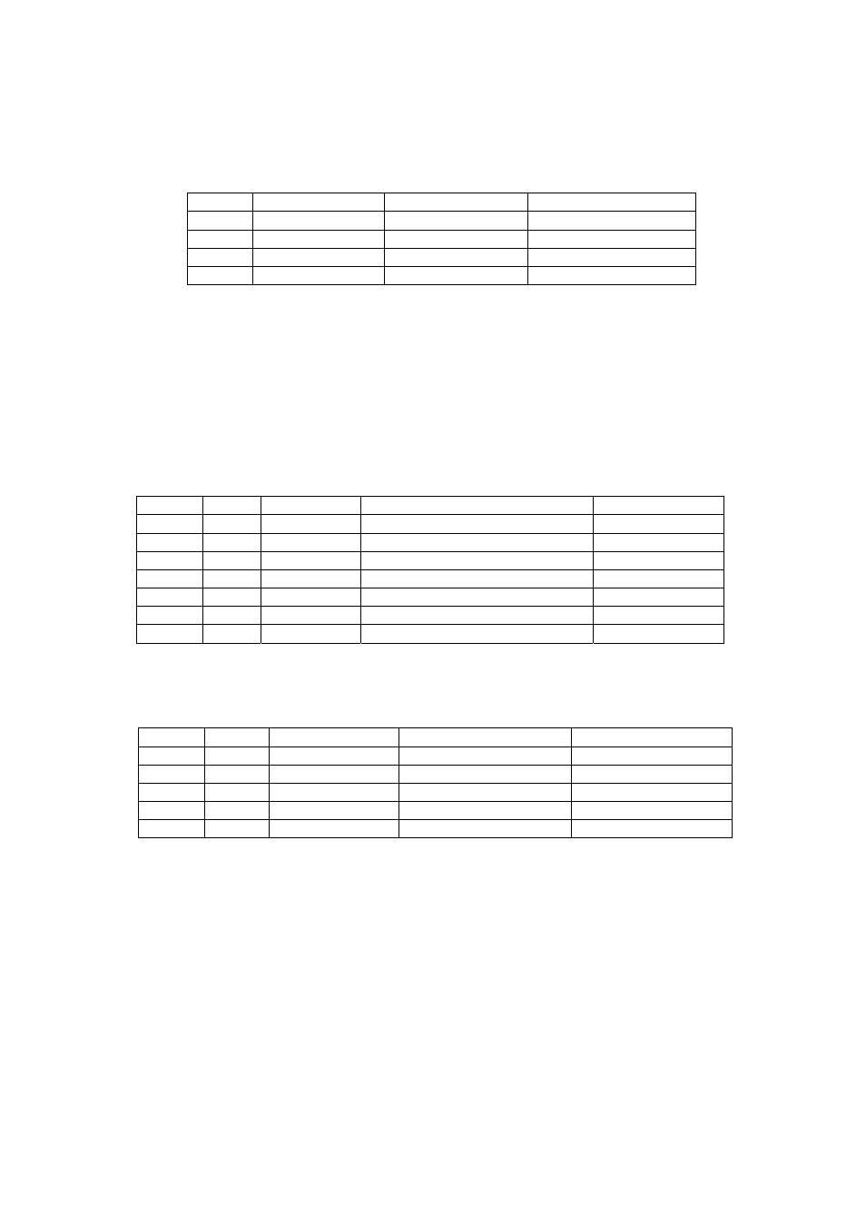
3.3 Connecter Signal Details
1) CN1: Power Input Connecter
Printer side: TCS7960-5320177(Hoshiden) or equivalent
Adaptor side: TCP8927-531177, TCP8927-631177,
TCP8935-531177(Hoshiden)equivalent
(Hoshiden)
or
Equivalent
Pin No.
Signal name
Input/Output
Function
1
VH
Input
Power DC +24V
2 GND
- Power
ground
3 N.C
-
Shell FG
- FG
*A sufficient volume of power supply is required to maintain print quality due to high peak current
that may run according to printing contents.
*If power supply cable is excessively long, the operation may become unstable. Cable should be
as short as possible. If not available, connect cables near the printer and place an electrolysis
condenser of 2200µ between power supply and ground. Voltage resistance should be higher
than 35V.
2) CN2: Serial Data signal input connector (Multiple Interface type only)
Printer side: JEC-9P (JST) or equivalent
Host side: JEC-9S (JST) or equivalent
Pin
No. Signal Input/Output
Function
Remark
2
RXD
Input
Serial receiving data
3
TXD
Output
Serial transmitting data
4
RTS
Output
Receiving permission signal
Connect to No.7
5 GND
- Singnal
ground
7
RTS
Output
Receiving permission signal
Connect to No. 4
8
CTS
Input
Transmit permission signal
1, 6, 9
N.C
-
3) CN3: USB data signal input connector
Printer side: B jack DUSB-BRA42-T11 (DDK) or equivalent
Host side: B plug or equivalent
Pin No. Signal
Input / Output
Function
Remark
1
VBUS
Input
Power line
Non twist power line
2
D-
Input and output
Data line
Twist pair signal line
3
D+
Input and output
Data line
Twist pair signal line
4
GND
-
Power line
Non twist power line
Shell Shield
-
* Use USB cable which conforms to the standard (V2.0 FULL SPEED)
* We shall not be liable for operation using the connector not comformed with the standard.