Rice Lake PR5220 Ethernet Transmitter User Manual
Rice Lake Scales
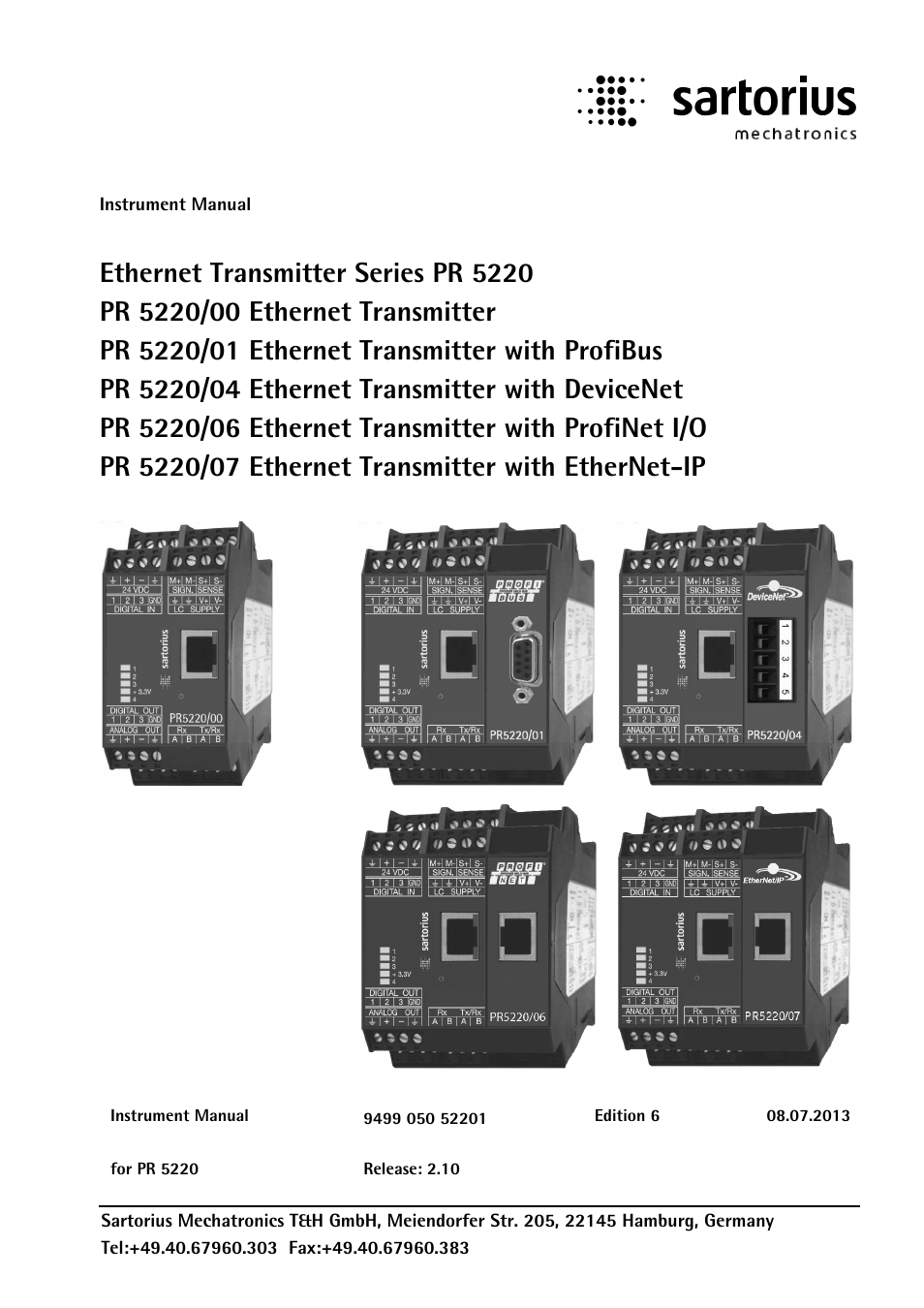
Table of contents
Document Outline
- 9499 050 52201
- Table of Contents
- 1 Safety Information
- 2 Ethernet Transmitter Series
- 3 Installing the Instrument
- 3.1 Connections
- 3.1.1 Network Port
- 3.1.2 RS-485 Interface
- 3.1.3 Analog Output
- 3.1.4 Optocoupler Inputs
- 3.1.5 Optocoupler Outputs
- 3.1.6 Load Cell Connection
- 3.1.7 Connecting Analog Platforms (CAP...)
- 3.1.8 Connecting xBPI Platforms (IS...)
- 3.1.9 Connection of Digital Load Cells
- 3.1.10 ProfiBus Interface (PR 5220/01 only)
- 3.1.11 DeviceNet Interface (PR 5220/04 only)
- 3.1.12 ProfiNet I/O Interface (PR 5220/06 only)
- 3.1.13 EtherNet-IP Interface (PR 5220/07 only)
- 3.1 Connections
- 4 Commissioning
- 4.1 Data Backup/Power Failure
- 4.2 Switching on the Instrument
- 4.3 Configuration and Calibration
- 4.3.1 Connecting the Device to the Network and Finding out the IP address
- 4.3.2 Resetting the Instrument/Activating Network'DHCP'
- 4.3.3 Searching the Instrument in the Network Using 'IndicatorBrowser'
- 4.3.4 Operation Using the VNC Program
- 4.3.5 Operation Using Internet Browser
- 4.3.6 INFO Function
- 4.3.7 Setup Function (VNC)
- 4.3.8 Setup Menu
- 4.4 Calibration Weighing Point ‚Internal A’
- 4.4.1 Displaying Calibration Data
- 4.4.2 Selecting the Calibration Mode
- 4.4.3 Determining the Maximum Capacity (Max)
- 4.4.4 Determining the Scale Interval
- 4.4.5 Determining the Dead Load
- 4.4.6 Calibration with Weight (by Load)
- 4.4.7 Calibration with mV/V Value [by mV/V]
- 4.4.8 Calibration with Load Cell Data (“Smart Calibration“)
- 4.4.9 Subsequent Dead Load Correction
- 4.4.10 Linearization
- 4.4.11 Test Value Determination/Display
- 4.4.12 Finishing/Saving the Calibration
- 4.4.13 Parameter Input
- 4.5 Calibrating an xBPI Scale
- 4.5.1 xBPI Set-up for Serial Port
- 4.5.2 xBPI Scale Function
- 4.5.3 xBPI Platform Configuration
- 4.5.4 xBPI Scale Parameter
- 4.5.5 xBPI Parameter Tables
- 4.5.6 xBPI Setting Dead Load
- 4.5.7 xBPI Calibration with the User Weight
- 4.5.8 xBPI Calibration with Automatic Weight Detection
- 4.5.9 xBPI Calibration with Default Weight
- 4.5.10 xBPI Calibration with Built-in Weight
- 4.6 Calibrating Digital Load Cells Type ‘Pendeo®’
- 4.6.1 General Information
- 4.6.2 Viewing the Interfaces
- 4.6.3 Selecting and Setting up the Interface
- 4.6.4 Selecting the Load Cell Type
- 4.6.5 Adjustment Sequence
- 4.6.6 Search for Load Cells
- 4.6.7 Assigning Load Cells
- 4.6.8 Calibrating Load Cells
- 4.6.9 Corner Correction
- 4.6.10 Finishing/Saving the Calibration
- 4.6.11 Parameter Input
- 4.6.12 Subsequent Dead Load Correction
- 4.7 Configuring General Parameters
- 4.8 Configuring Limit Values
- 4.9 Digital Outputs and Inputs
- 4.10 Analog Output
- 4.11 Logfiles
- 4.12 Saving Configuration Data [Backup of EAROM]
- 5 J-Bus/ModBus Protocol
- 6 SMA Protocol
- 7 Fieldbus Interface
- 8 Global SPM Variables
- 9 Configuration Print-Out
- 10 Extended Functions
- 11 Repairs and Maintenance
- 12 Disposal
- 13 Error Messages
- 14 Specifications
- 15 Index
- 16 Appendix