9750a – Rice Lake MSI-9750A CellScale RF Portable Indicator User Manual
Page 70
Page 70 MSI-9750A RF Remote Indicator • User Guide
9750A
HANDHELD RF REMOTE INDICATOR for
C
ELL
S
CALE
®
SETUP SELECT MENU
1 Function Keys
2 Set Points
3 System
4 Password Locks
5 Bar Code
6 Total
7 MORE 1/2
BAR CODE SETUP MENU
1 Bar Code 1 Buffer
2 Bar Code 2 Buffer
3 Bar Code 3 Buffer
4 Bar Code 4 Buffer
5 User Str Buffer
6 User Str Buffer
7 Auto Save Serial
BAR CODE X IS SENT TO
1 CellScale Comm 1
2 All CS Outputs
3 CS RF Host 3
4 CS RF Host 4
5 CS RF Host 5
6 9750 Printer Port
7 String Buffer Only
Usr StrX IS SENT TO
1 CellScale Comm 1
2 All CS Outputs
3 CS RF Host 3
4 CS RF Host 4
5 CS RF Host 5
6 9750 Printer Port
7 String Buffer Only
7 Auto Start BC1 OFF
7 Auto Start BC1 ON
1 Bar Code 1
XX
Chars
2 Bar Code 2
XX Chars
3 Bar Code 3
OFF
4 Bar Code 4
OFF
5 Usr Str 1
OFF
6 Usr Str 2
OFF
7 AutoStart BC 1
OFF
AUTO CHARS BARCODE
1
ESC exits no change
ENTER saves value
0-9 insert
min = 0, max = 64
^ incs, v decs digit
SETUP SELECT MENU
BAR CODE SETUP MENU
BAR CODE
X
IS SENT TO
USER STR
X
IS SENT TO
MINIMUM STRING SIZE
AUTO CHARS BARCODE
X
1
ESC
!
SETUP
5
MNO
2
DEF
1
ABC
3
GHI
6
PQR
5
MNO
4
JKL
7
STU
1-6
7
STU
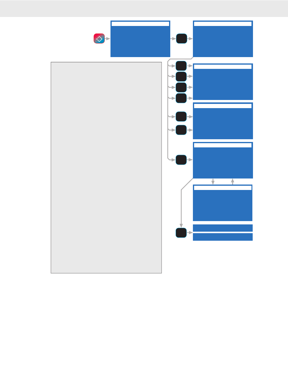
To set up the Bar Code reader, press
SETUP
then
[5]
.
1) BarCode 1 – The sub-menu designates the output
mode when data comes in for Bar Code 1.
[1]
Select-
ing 1 will send the data to the master CellScale’s
Comm Port 1.
[2]
Bar Code 1 data will be sent to all
of the CellScales active ports, both direct connect, and
RF connected.
[3]
BC1 data is sent to the CellScale
RF Host 3.
[4]
BC1 data is sent to the CellScale RF
Host 4.
[5]
BC1 data is sent to the CellScale RF Host
5.
[6]
BC1 data is sent to the transmit line on the
9750A Comm Port.
[7]
No action, the Bar Code data
is stored in the Bar Code 1 buffer and is available for
inclusion in print strings or sent to the display.
2-4) BarCode 2-4 – Same options as above.
5) User String 1 – The title here will change if the User
String 1 function key was titled by the user. For
example it might read “Operator” indicating the User
String 1 is used to store an Operator ID. “Sent To”
options are the same as above.
6) User String 2 – The title here will change if the User
String 2 function key was titled by the user. For
example it might read “Customer” indicating the User
String 1 is used to store an Customer ID. “Sent To”
options are the same as above.
7) Auto Save Serial – Pressing
[7]
brings up the MINI-
MUM STRING SIZE menu. Used to designate the
minimum acceptable size of autoentered data. For
example; Suppose the operator ID stored in User
String 1 has to be 6 characters or more. By setting the
Auto Enter size to 6, a bar code or text entry that is
too small will not automatically enter into the desig-
nated string. The text entry screem will appear if the
input code is too small, allowing the user to reject the
data (press
ESC
), accept the data (press
ENTER
), or
append to the data with the alphanumeric keypad.
MINIMUM STRING SIZE MENU
1-4) Pressing 1-4 brings up a numeric entry screen that allows you to set the minimum string size of the four
available Bar Code Strings . Bar Code strings can be up to 64 characters in length.
5-6) Pressing 5 or 6 allows setting the minimum size of the ID User Strings. User Strings are limited to 20 char-
acters.
7) AutoStart BC 1 – Turning “Auto Start Bar Code 1” on will designate any data coming in the Comm Port,
while in the weight display mode, will automatically input into the Bar Code 1 buffer. This eliminates the
need to fi rst push a function key to tell the 9750A where to put the data.