Rice Lake MSI-9750A CellScale RF Portable Indicator User Manual
Page 65
MSI CellScale
®
System • 9750A User Guide Page 65
MEASUREMENT SYSTEMS INTERNATIONAL
Firmware Version 5-XX for 2450 Modems
Menu Description
1) Output Memory 1 – Pressing
[1]
will output all data in Data Logging Memory 1 to the Comm Port. Connect
the 9750A to an appropriate terminal or computer before using this function.
2) Output Memory 2 – Pressing
[2]
will output all data in Data Logging Memory 2 to the Comm Port. Connect
the 9750A to an appropriate terminal or computer before using this function.
3) Abort Output – Press
[3]
to abort the output function. The data output will cease, and the data will be left
intact, with the start of data pointer reset to the beginning of the memory fi le.
4) Erase Memory 1 – Press
[4]
to erase all data in Memory 1. A caution screen appears requiring confi rmation
before erasing the data. Once erased, the data is gone, so make sure that it has been transferred using the
Output commands before erasing the data. The line indicates the per cent used capacity of memory 1. It will
read “CLR” when empty.
5) Erase Memory 2 – Press
[5]
to erase all data in Memory 2. A caution screen appears requiring confi rmation
before erasing the data. The line indicates the per cent used capacity of memory 2. It will read “CLR” when
empty.
6) FKey to Memory X – Use the
[6]
key to choose which memory the data is stored in when using the uncom-
mitted “Save to Memory” function key. Toggles between Memory 1 and Memory 2.
7) AutoPrint to Memory – Use the
[7]
key to bring up the Auto Print to Memory sub menu. This feature allows
Automatic data logging using the Trigger Print modes (See Section 9). By using, for example, “Print On
Load”, every time a steady weight is reached, the weight will be automatically recorded. Using the Continuous
print mode combined with a user set interval, weight data can be recorded on any time interval. AutoPrint to
Memory uses the main print string only. The Aux String is still available for manual data storage.
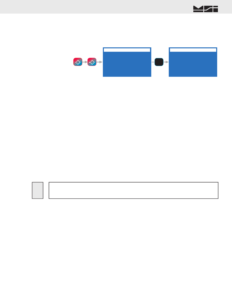
DATA LOGGING
1 Output Memory 1
2 Output Memory 2
3 Abort Output
4 Erase Memory 1
XX%
5 Erase Memory 2
XX%
6 FKey to Memory 1
7 AutoPrint to Mem 1
AUTO PRINT TO MEMORY
1 Print to Memory 1
2 Print to Memory 2
3 Auto Log Msg
ON
4 Auto Clr IDStr1
OFF
5 Auto Clr IDStr2
OFF
6 Bar1
OFF
8 Bar3
OFF
7 Bar2
OFF
9 Bar4
OFF
AUTO PRINT TO MEMORY
DATA LOGGING
7
STU
ESC
!
SETUP
NET/GROSS
B/G
Erasing the data logging memory is permanent. The data will be lost. Make sure the
data is no longer needed before using the erase memory functions. Erasing data logging
memory does not effect any other CellScale memory functions.
!
Auto Print to Memory
The “Auto Print to Memory” sub menu has nine choices:
1) Print to Mem 1 – Automatic print data is redirected to data logging memory 1. Only pressing the Print key
will generate an output to the Comm Port.
2) Print to Mem 2 – Automatic print data is redirected to data logging memory 2. Only pressing the Print key
will generate an output to the Comm Port.
3) Auto Log Msg – When using the auto data logging features, the default Auto Log Message is on to alert
the user that data has been stored. Use this mode for “Auto Print to Memory” modes with data storage that
doesn’t occur very often. If using continuous printing to memory modes or other modes that happen rapidly,
turn the “Auto Log Msg” off so that the message won’t interfere with other screen functions.
4) Auto Clr IDStr1 – When ON, the ID String 1 is cleared after every stored weighment. This prevents unwanted
duplication of data. When OFF the string is left intact until manually changed.
5) Auto Clr IDStr2 – When ON, the ID String 2 is cleared after every stored weighment. This prevents unwanted
duplication of data. When OFF the string is left intact until manually changed.
6) Bar1 – When ON, data in the Bar Code String 1 will be saved along with the confi gured print string.
7) Bar2 – When ON, data in the Bar Code String 2 will be saved along with the confi gured print string.
8) Bar3 – When ON, data in the Bar Code String 3 will be saved along with the confi gured print string.
9) Bar4 – When ON, data in the Bar Code String 4 will be saved along with the confi gured print string.
DATA LOGGING CONTROL MENU
The Data Logging Control Menu provides a means to upload stored data, and erase the data logging memory
locations.
The Data Logging Control Menu is reached by pressing
SETUP
followed by
NET/GROSS
. Alternately the
menu can be reached through the Comm Port and Strings Menu.