9750a – Rice Lake MSI-9750A CellScale RF Portable Indicator User Manual
Page 56
Page 56 MSI-9750A RF Remote Indicator • User Guide
9750A
HANDHELD RF REMOTE INDICATOR for
C
ELL
S
CALE
®
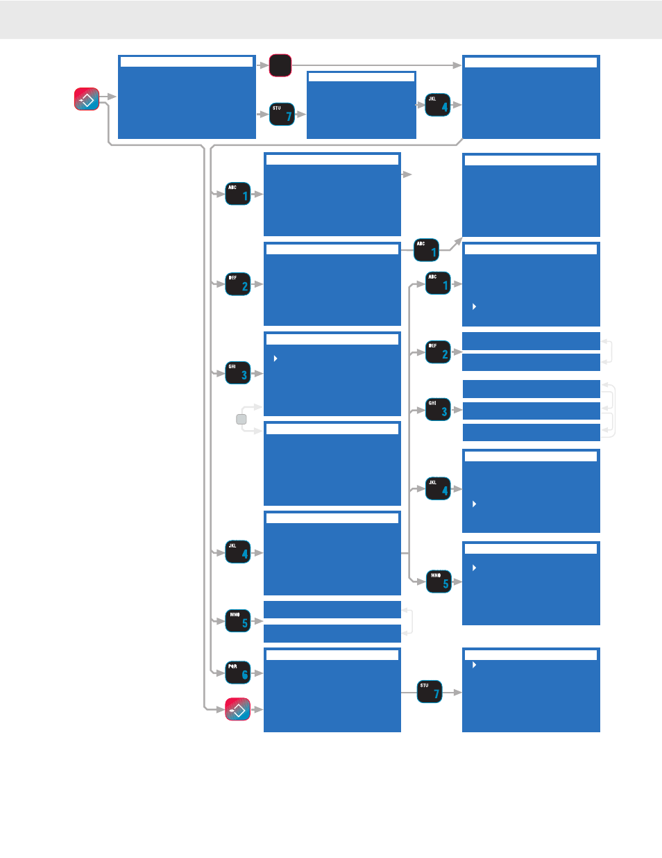
SETUP SELECT MENU
1 Function Keys
2 Set Points
3 System
4 Password Locks
5 Display Preview
6 Total
7 MORE 1/2
COMM PORT 2
1 Enter/Edit Strings
2 Output Interval
3 Control Settings
4 Serial Settings
5 Motion Check ON
6 Data Logging
SETUP SELECT MENU
1 Channel & Calibrate
2 Display
3 RF Modem
4 Comm 2 & Strings
5 Product ID Codes
6 Tare
7 MORE 2/2
BAUD RATE
1 3ØØ 8 19.2k
2 6ØØ 9 28.8k
3 12ШШ Ш 38.4k
4 24ØØ F1 57.6k
5 48ØØ F2 76.8k
6 96ØØ F3 115.2k
7 14.4k F4 23Ø.4k
2 Data Bits 7
2 Data Bits 8
HANDSHAKING
1 Hardware DCE
2 Hardware DTE
3 Hardware RTR/CTS
4 None
5 Software XON/XOFF
MODE
1 Duplex
2 Listen
3 Off
4 Talk
Text Editing
TT
Screen. See
general text
editing
section.
INTERVAL MILLISECOND
ESC exits no change
ENTER saves value
Ø-9 replaces value
5Ø
min = Ø, max = 95Ø
^ incs, v decs digit
Shortcut
6
TRIGGER PRINT ON
-Current Mode-
1 Total
2 Set Point 1 (SP1)
3 Set Point 2 (SP2)
4 SP1 And SP2
5 SP1 Or SP2
6 MORE 2/2
TRIGGER PRINT ON
-Current Mode-
1 Continuously
2 Send/Print Key
3 Comm 2 CTS
4 Weight Change
5 Stable Load
6 MORE 1/2
COMM 1 STRINGS
1 Data Out String
2 End of Line
3 Start of Line
4 Wait Character
5 Aux String
6 Ack String
7 Overload String
OUTPUT INTERVAL
Print Once on Trig
1 Milliseconds
2 Seconds
3 Minutes
4 Hours
5 Days
CLR = Print Once
SERIAL SETTINGS
1 Baud Rate 96ØØ
2 Data Bits 8
3 Parity NONE
4 Handshake NONE
5 Mode DUPLEX
6 Setup Settings Dump
5 Motion Check OFF
5 Motion Check ON
DATA LOGGING
1 Output Memory 1
2 Output Memory 2
3 Abort Output
4 Erase Memory 1 XX%
5 Erase Memory 2 XX%
6 FKey to Memory 1
7 AutoPrint to Mem 1
AUTO PRINT TO MEMORY
1 Print to Memory 1
2 Print to Memory 2
3 Auto Log Msg OFF
4 Auto Clr IDStr1 OFF
5 Auto Clr IDStr2 OFF
6 Bar1 OFF 8 Bar3 OFF
7 Bar2 OFF 9 Bar4 OFF
3 Parity EVEN
3 Parity NONE
3 Parity ODD
1-5 Key
1 Key shown
for example
NET/GROSS
B/G
COMM 1 STRINGS
OUTPUT INTERVAL
TRIGGER PRINT ON
TRIGGER PRINT ON
SERIAL SETTINGS
DATA LOGGING
COMM PORT 2
SETUP SELECT MENU
INTERVAL MILLISECONDS
BAUD RATE
HANDSHAKING
MODE
AUTO PRINT TO MEMORY
SETUP SELECT MENU
ESC
!
SETUP
IN
F3
SEND/PRINT
for software handshaking commonly used in communicating with computers. Use “Hardware DCE”
[2]
for interfacing with
devices with an RTS output and CTS input. Use “Hardware DTE”
[3]
if the 9750A must produce RTS as an output and CTS
as an input. “Hardware RTR/CTS”
[4]
protocol provides a symmetrical interface. When a device is ready to receive data, i.e.,
there is no unread data in the serial port receive register, the device asserts the RTR signal. A device does not begin transmitting
data until the CTS signal is asserted. Use NONE
[1]
(default) for situations where no handshaking is required or possible. It is
recommended that hardware handshaking is used for all high baud rate applications (>19200 Baud).
[3]
TRIGGER PRINT ON: The
“Trigger Print On’ menu designates
the condition that causes the 9750A
to output data. The Send / Print key
will always work unless specifi -
cally locked out or the function key
is reassigned. When the designated
trigger condition occurs, the print
string specifi ed in the “Data Out
String” will be output on Comm 1. If
the “Motion Check” parameter is set
to “ON”, the weight must be stable
before the 9750A will output data.
If a valid trigger occurs, the 9750A
will wait for the next settled (out of
Motion) reading before it will output
data. See descriptions of the Trigger
Print modes in the “Trigger Print”
section above.
[4]
SERIAL SETTINGS: The
Serial Settings menu is used to set
standard Comm Port parameters.
See “To Set The Baud Rate” for an
example of how to use these setting
menus.
STOP BITS: Stop Bits are not changeable and
set to 1.
1) BAUD RATE: Standard Baud
Rates available are 300, 600,
1200, 2400, 4800, 9600, 14400,
19200, 28800, 38400, 57600,
76800, 115200, and 230400. The
9750A defaults to 9600 Baud.
2) DATA BITS: Either 7 or 8 Data
Bits can be set. If 7 bit mode is
set, Data Characters above 127dec
cannot be sent or received. The
default is 8 bits.
3) PARITY: Parity mode is NONE
Parity, EVEN or ODD. The
9750A defaults to “NO Parity”.
4) HANDSHAKE: Comm Port
Handshaking is set in this menu.
Use “Software XON/XOFF”
[5]