13 hard drive(s) are not recognized, 5 led information, Led information – Kontron NSW1U IP Network Server User Manual
Page 89: Section 7.5, For a descri
Kontron IP Network Server NSW1U
December 2009
Product Guide, rev. 1.4
89
Troubleshooting—NSW1U Network Server
If you suspect that a transient voltage spike, power outage, or brownout might have occurred,
reload the software and try running it again. Symptoms of voltage spikes include a flickering
video display, unexpected system reboots, and the system not responding to user commands.
Note:
For AC power, if you are getting random errors in your data files, they may be getting
corrupted by voltage spikes on your power line. If you are experiencing any of the
above symptoms that might indicate voltage spikes on the power line, you may want to
install a surge suppressor between the power outlet and the system power cord.
7.4.12
Devices are not Recognized Under Device Manager (Windows*
Operating System)
The Windows* operating systems do not include all of the drivers for the Intel
®
chipsets, onboard
NICs, and other components. See Go
r a link to the current
drivers and chipset files.
7.4.13
Hard Drive(s) are not Recognized
Check the following:
Make sure the drive is not disabled in BIOS Setup.
Make sure the drive is connected correctly and that it is plugged into the power supply.
Make sure the drive is compatible. Go to
a link to the list
tested drives.
Make sure you have not exceeded the power budget for the server
link to software to check your power budget.
7.5
LED Information
The Intel
®
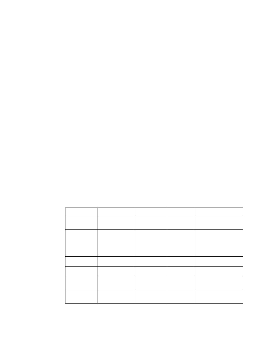
Server Board S5000PHB server board includes LEDs that can aid in troubleshooting your
system. A table of these LEDs with a description of their use is listed below.
Table 8.
LED Definitions
LED Name
Function
Location
Color
Notes
ID
Aid in server
identification from
the back panel
Control panel and
board rear left
corner
Blue
Press ID LED button or user
Server Management
software to turn on the LED.
System fault
Visible fault warning
Control panel and
board rear left
corner
Green or
Amber
Green = No Fault
Green blinking = degraded
Amber = critical error or
non-recoverable
Amber blinking = non-
critical error
SATA drive
activity
Control panel
Control panel
Green
Blinking = Activity. No action
required.
Memory fault 1–6
Identify failing
memory module
DIMM end rear of
board
Amber
On = Fault
Diagnostic LEDs.
1–4 (LSB, bit1,
bit2, MSB)
Displays port 80
POST codes
Center back edge
of board
Each LED can
be Off, Green,
Amber, Red
See the POST code table
CPU Fan Fault
Identify fan failure
EFP board by the
fan power
connector
Amber
On = Fault