7 server board connector and component locations, Server board connector and component locations – Kontron NSW1U IP Network Server User Manual
Page 21
Kontron IP Network Server NSW1U
December 2009
Product Guide, rev. 1.4
21
Kontron IP Network Server NSW1U Features—NSW1U Network Server
2.7
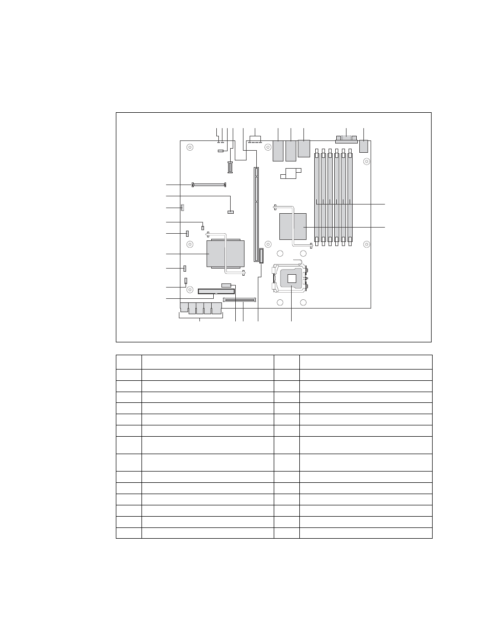
Server Board Connector and Component Locations
Figure 10.
IP Network Server NSW1U Components and Connector Location Diagram
Item
Description
Item
Description
A
System Identification LED (blue)
O
Battery
B
Status LED (green / amber)
P
Flex connector to EFP board
C
Serial Port B DSR / DCD jumper (J2A2)
Q
Serial Port A header
D
GCM connector
R
Main power connector
E
PCI Express/PCI-X riser card slot
S
PATA (IDE) connector
F
POST code gigantic LEDs
T
Password Clear jumper (J1H2)
G
Dual-port LAN connector (NSW1U-R and
NSW1U-B)
U
BIOS Bank Select jumper (J1G1)
H
Dual-port LAN connector (NSW1U-R and
NSW1U-B)
V
Intel
®
ESB2-E I/O controller hub
I
USB 2.0/RJ-45 serial port connector
W
CMOS Clear jumper (J1F1)
J
Video connector
X
BMC Force Update Jumper (J1E3)
K
PS/2 keyboard and mouse connector
Y
3-pin IPMB header
L
FBDIMM slots
Z
Processor select jumper
M
Intel
®
500P memory controller hub
AA
Remote management connector
N
Processor socket
AF000750
CD
F
G
H
J
I
E
AB
O
N
P
K
L
Y
AA
Q
M
S
U
T
R
V
W
X
Z