4 installing or replacing a pci add-in card, Installing or replacing a pci add-in card – Kontron NSW1U IP Network Server User Manual
Page 51
Kontron IP Network Server NSW1U
December 2009
Product Guide, rev. 1.4
51
Optional Component Installation Procedures—NSW1U Network Server
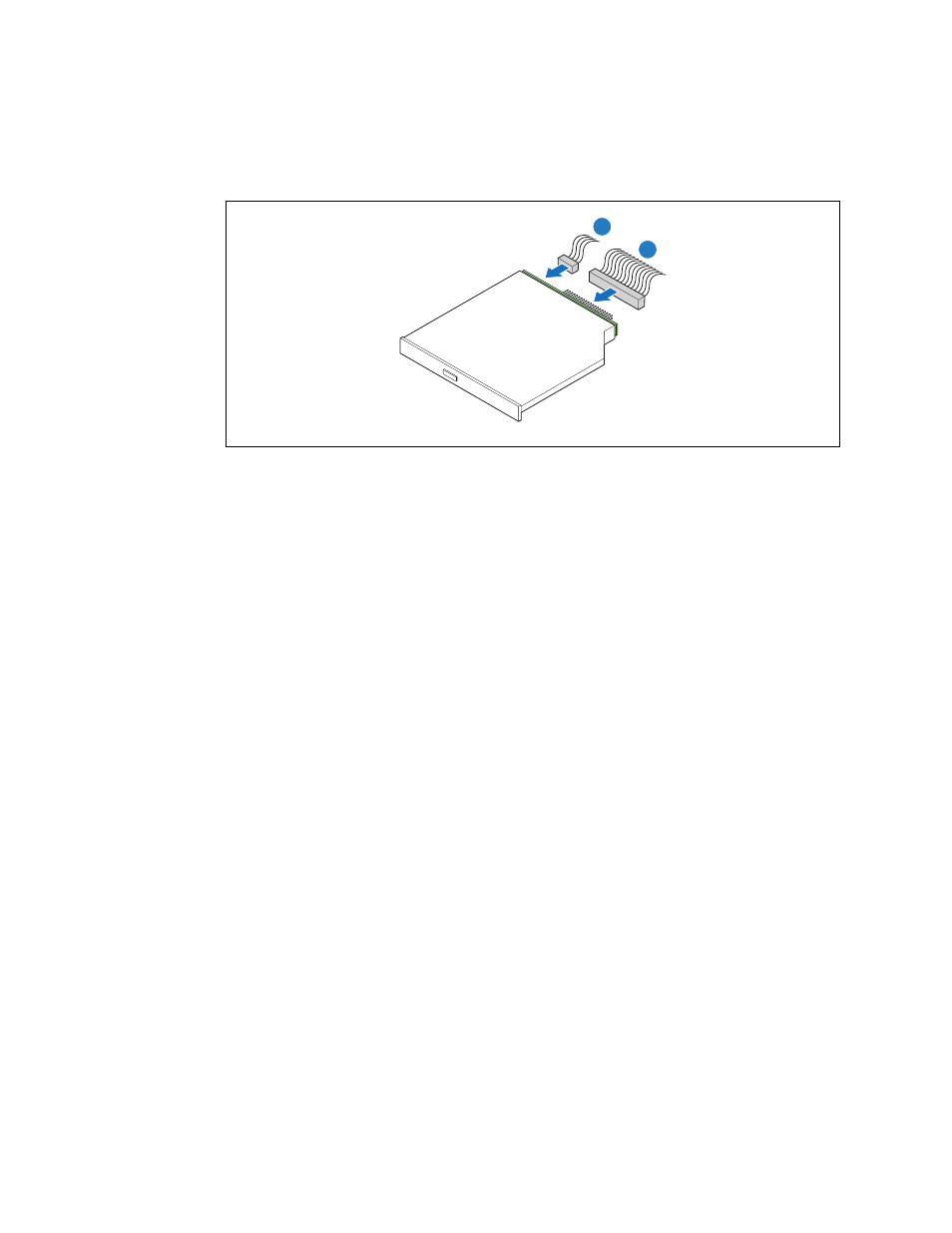
5. Connect the power and data cables onto the interposer board. (
, “A” and “B”)
6. If this is the last task you are performing, replace the front panel and the top cover of the chassis.
Reconnect all the external devices and plug in the power cord(s).
For information about mounting the server in a rack, see
Section 3.5, “Installing the Server into a
4.4
Installing or Replacing a PCI Add-in Card
The riser card assembly is installed in the super slot located in the middle of the S5000PHB server
board. (See
for this location.) The system is delivered with a PCI Express* riser
card attached to the riser card assembly. To use PCI-X* cards, this riser must be replaced with the
PCI-X riser card, which can be ordered as an accessory.
Note:
PCI/PCI-X/PCI Express add-in cards are referred to generically as “PCI cards” in the
following procedures.
To add a PCI card, remove the riser card assembly from the system. Ensure that the appropriate riser
card is attached to the assembly (PCIe by default) or replace it with the correct one (e.g, PCI-X
instead of PCIe), remove the I/O filler panel, then add the PCI or PCIe add-in card. This assembly is
then plugged back into the super slot connector on the S5000PHB server board server board. Refer to
the Intel® Server Board S5000PHB Technical Product Specification for the electrical characteristics
for the PCI/PCIe riser card assembly super slot.
Note:
Using a supported PCI/PCIe card is recommended. For a list of tested and supported
cards, see the Tested Hardware and Operating System List (THOL) at
earch for NSW1U, click on Product Downloads, and then
click on Compatability Matrix.
Figure 31.
Connecting the Optical Device Power and Data Cables
TS000410
A
B