Figure 43 – Kontron NSW1U IP Network Server User Manual
Page 60
NSW1U Network Server—Optional Component Installation Procedures
Kontron IP Network Server NSW1U
Product Guide, rev. 1.4
December 2009
60
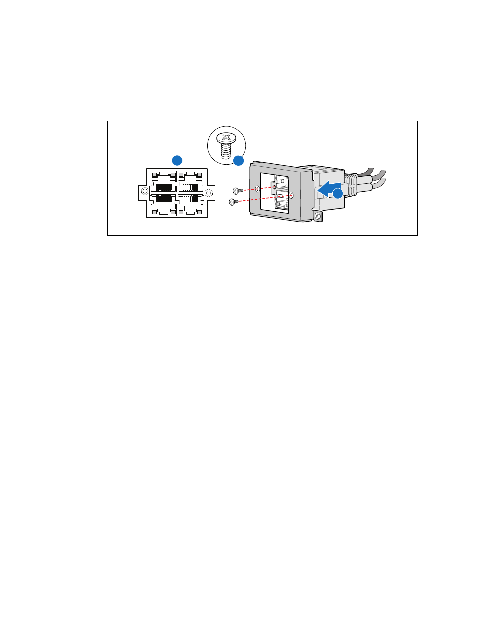
Note:
When viewed from the front, each port has a letter. Be sure to install the connector
with “A” and “C” at the top. Do not install the connector upside-down. (“A”)
7. Attach the connector using two screws, as shown. (“B”)
8. If this is the last task you are performing, replace the front panel, the processor air duct and the
top cover of the chassis. Reconnect all the external devices and plug in the power cord(s).
Figure 43.
Installing the Cable Connector into the Front Panel Escutcheon
AF000886
A
B
B
D
A
C
A