Figure 29 – Kontron NSW1U IP Network Server User Manual
Page 50
NSW1U Network Server—Optional Component Installation Procedures
Kontron IP Network Server NSW1U
Product Guide, rev. 1.4
December 2009
50
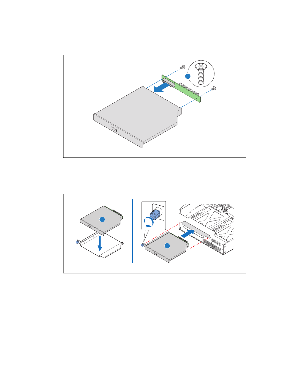
3. Place the optical device in the drive tray.
4. Insert the optical device/tray/interposer board assembly into the chassis and tighten the blue
thumbscrew. (
, “A” and “B”).
Figure 29.
Connecting the Interposer Board
f
Figure 30.
Installing the Optical Device
A
TS000408
A
B
TS000409